Last Updated – 17/09/2023
This is a basic procedure for how to safely remove/replace VRAM chips. This procedure uses a preheater to warm the whole card, but many people also successfully remove/replace VRAM chips using a hot air station alone (which often requires a higher hot air temperature). It always looks easy when watching experts do this procedure, and with experience, probably it can indeed become very routine. However, like most procedures, there are risks and it’s easy to underestimate the value of experience. So, if it’s the first time you’re trying it, I recommend practising until you feel comfortable on less valuable or scrap cards. I am learning too and trying to refine this procedure as I go, so all thoughts are very welcome, please do add comments.
How do you know you have a VRAM issue on your GPU and which chip is faulty?
This deserves a guide in it’s own right and even if you’re sure you have a VRAM issue, it’s clearly good to know which chip or chips are faulty to avoid having to take guesses and potentially replace good chips. I highly recommend you invest some time to obtain a suitable tool for VRAM testing before attempting to replace VRAM chips.
Some clues that there could be a VRAM issue:
Error 43 in Windows device manager – Whilst VRAM is not the only cause of the generic error 43 (can also be BIOS or core-related), it is a common cause.
Blank screen on boot, after a few seconds the backlight on the monitor comes on without a picture -This sign is only for Nvidia 10 series cards, but be a clue of a VRAM issue.
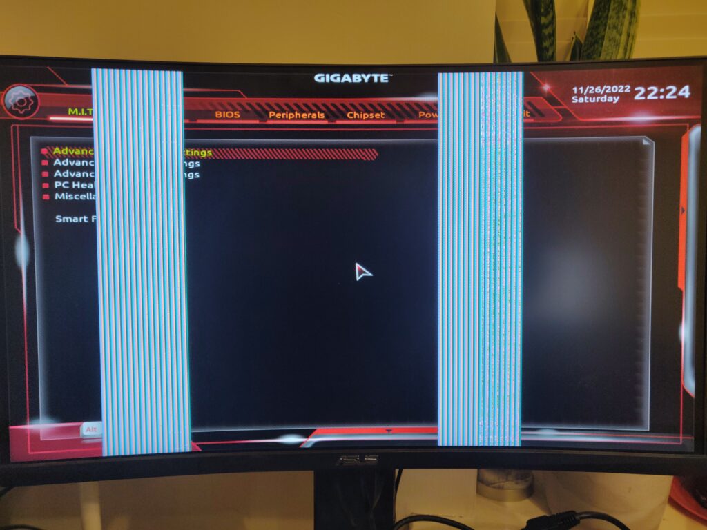
Two vertical bar artefacts shown – This is for AMD/Radeon cards and can be very helpful, as the position of the vertical artefacts indicates the problem VRAM channel. An example can be seen below.
See also this nice guide on how to work out the failing VRAM channel https://repair.wiki/w/AMD_Memory_Testing_Guide.
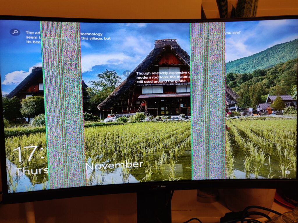
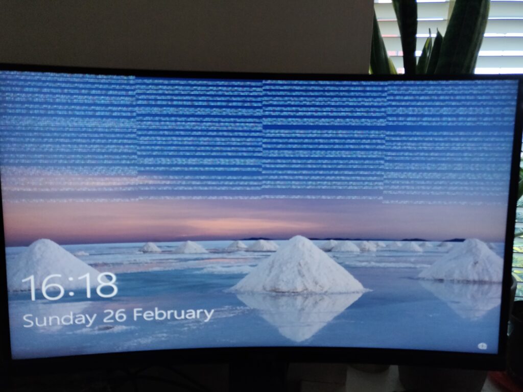
For Nvidia cards, artefacts can be a sign of memory corruption, but unfortunately don’t have the same pattern as with the AMD/Radeon ones shown above. Here is an example, but they can take many forms:
Memory testing software
There are several memory testing applications that can be hugely helpful in not only confirming the diagnosis of a VRAM issue, but better still, helping you identify the exact chip or memory channel that is showing a test error. These tools are not officially available, so it is necessary to search for videos and links to obtain copies and instructions. The variety and depth of information needed to reliably make use of these tools is a topic for a separate guide. Here are a couple of the main tools to look for:
- NVidia cards – MATS/MODS. There are many versions, they can be extremely useful and detailed in the information they provide.
- AMD/Radeon cards – Tserver. This program usually only tells you the faulty channel e.g. A, but is also very useful.
There are a variety of other memory test related tools. Here are some links/names you might also want to look into:
- NVMT
- AMD Graphics Tool (AGT)
- Nice guide https://repair.wiki/w/Nvidia_Memory_Testing_Guide
- Nice video https://www.youtube.com/watch?v=QUWoz9vvHgM
Memory tests pass but you still suspect memory corruption?
Unfortunately, this can happen, but don’t give up. In cases like this, some tips are:
- Heat and physical pressure on the card – Sometimes a memory fault can only be present if the card gets hot or it is gently flexed in position. This is typical where one or more solder balls are damaged under the chip, causing a loss of connection with heat expansion and/or the weight/position of the card. You simulate this by heating the card with a hot air gun slightly whilst testing.
- Frequency/Workload – This can also happen where the VRAM chip becomes faulty only when tested under full load (which some memory test tools may not do by default). If the card runs fine with clocked-down memory frequency, this could be an indicator. Likewise, using a tool that is capable of over-clocking the VRAM might reveal the fault.
- Repeat the memory test several times or with increased settings – Test more of the memory or just ‘getting lucky’ on certain test runs can sometimes detect otherwise undetected faults.
Where to get or buy replacement VRAM chips?
There are two options:
Option 1 – Buy VRAM chips
I generally take this option, often just to reduce work. I generally buy VRAM chips on Alliexpress, my favourite seller there is Shenzhen Hong Ming Electronics Co https://www.aliexpress.com/store/1738577?spm=a2g0o.productlist.main.2.38be4180bidKzs. I have always found them reliable.
Option 2 – Find a donor card with the exact same or compatible VRAM chip
For this option, you need to find an otherwise unfixable donor card (e.g. on Ebay) and have some time to refurbish or reball the chip – see Graphics Card VRAM Reball Procedure. This option is a skill in itself, nice way to save money and recycle parts.
When selecting donor cards, be careful to target those with issues that should leave the VRAM chips undamaged, for example, check the VMem resistance – shorts here obviously could damage all VRAM chips on the card!
Prep & Tools
I would say the following tools are essential.
Essential
- Hot air station – I use the heater without any nozzle fitted. Better quality stations can quickly pay off.
- Soldering iron with flat tip e.g. bc3 or similar for cleaning pads
- Flux – I use a syringe dispensed, gel-type flux e.g. AMTECH NC-559-ASM, or Mechanic AD-559
- Leaded solder & solder wick/braid – For cleaning pads following removal. I typically use a 1mm braid. Wider braids can also work, but be careful not to let it stick and rip pads when cleaning!
- A suction tool or tweers for chip removal
I also use the following optional tools. It’s possible not to, but I often find them very helpful.
Nice To Have
- PCB preheater – Nice to have, allows for lower hot air temps and more margin for error. However, it’s completely possible to successfully replace VRAM chips without a preheater (many do).
- Microscope or some form of magnification – Magnification is often useful for cleaning and inspecting pads following chip removal. A microscope can become essential in the case where pads must be repaired.
Before You Start
- ALWAYS Have a measured position become getting to work:
- If possible, save any test results from analysis software (e.g. MATS, tserver) before making a start. Even if you already know a certain chip has errors, it can help to know the state before changing anything.
- Measure the resistance of the Vmem rail before and after (don’t let shorts make things harder!).
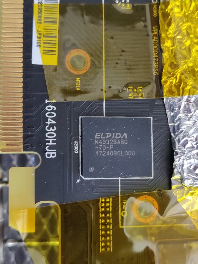
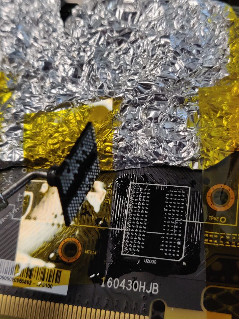
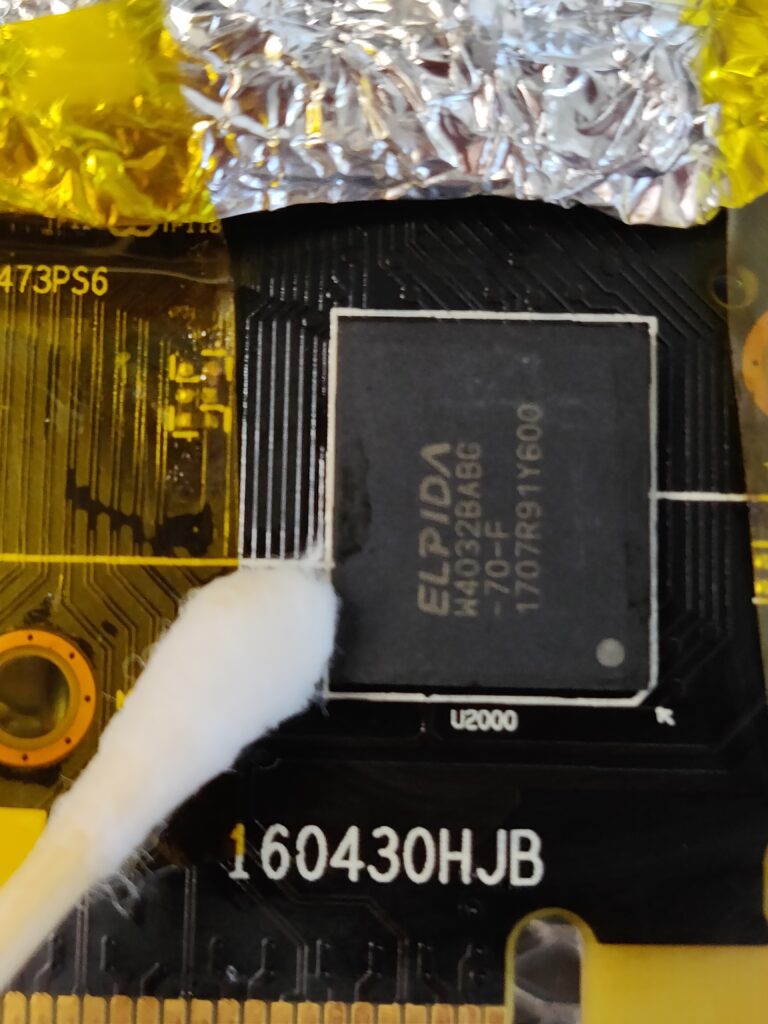
- GOOD TO cover nearby sensitive components (e.g. electrolytic capacitors) with foil or Kapton tape.
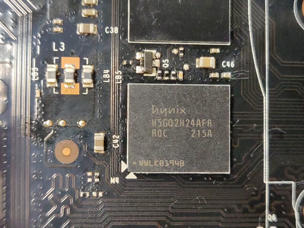
- GOOD TO make a quick plan for chip removal. For example, there are often small capacitors surrounding VRAM chips (consider taking a photo for easier replacement in the event they get dislodged).
General Tips
These tips are of course based on my experience, please don’t take them as expert advice. I am improving, but this is mainly to share the mistakes I have made.
- GOOD TO clean pads thoroughly and carefully. Plenty of flux. Sweep the pads with a soldering iron with a blob of solder first, trying not to drag the iron on the actual pads, and let the solder ball glide.
- BE CAREFUL not to overheat the chip i.e. if using higher heat (e.g. 400-450 deg C), be quicker, if using moderate heat don’t spend too long. The chip can get damaged. I have baked chips by overdoing the heating i.e. spending too long.
- GOOD TO commit to the ‘side nudge test’ to confirm solder is flowing – I personally had a problem doing this (I feared that I would dislodge the chip or cause solder balls to fuse). However, it’s probably worse to try to guess if the solder is flowing and often wastes time by having to repeat the process. Without the ‘nudge test’ it is easy to underheat (see example here MSI GTX 1050 2Gb) or worse, possibly overheat the chip.
- TRY NOT TO use loads of flux when soldering the new chip. Just a thin layer all over the pads is enough. Too much flux seems to lead to a higher chance of fused solder balls (i.e. two adjacent solder balls bridging together). It also doesn’t seem necessary to add lots or any flux when removing the chip, doing so isn’t a big deal, but tends to create more mess and smoke.
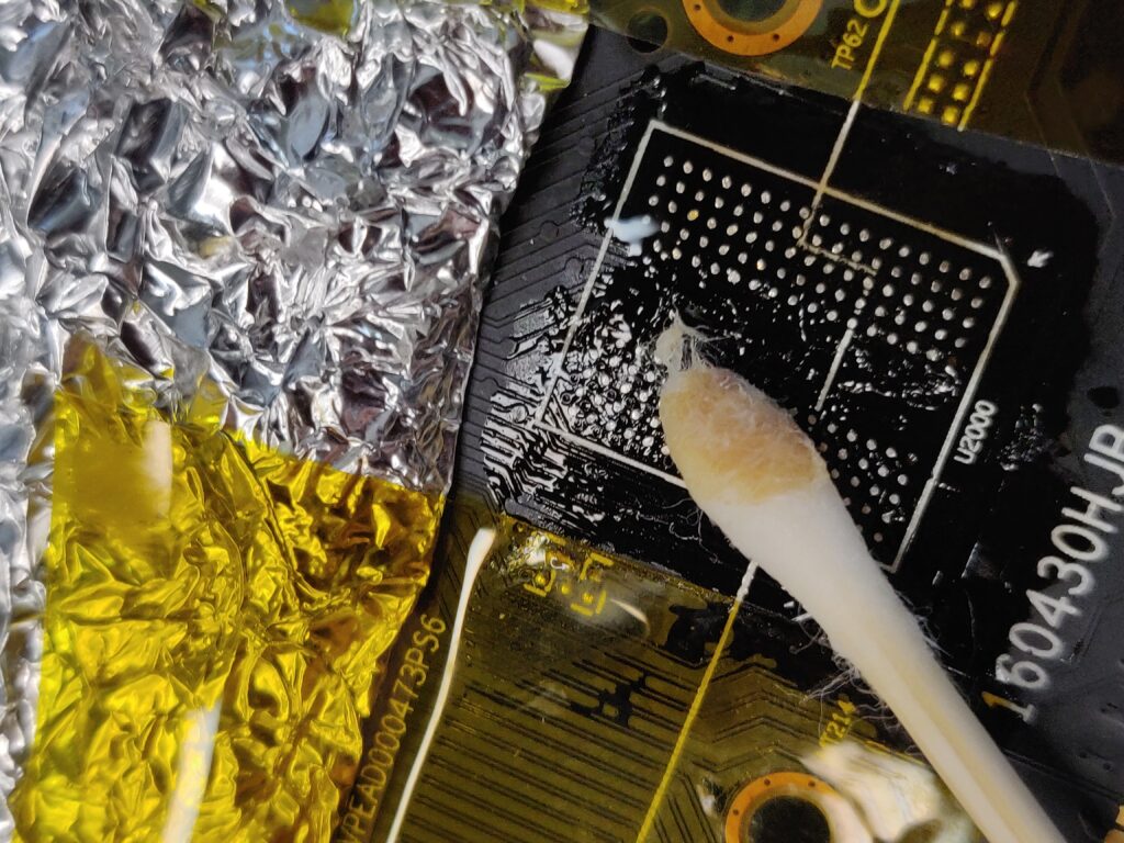
- GOOD TO clean the desoldered pads with IPA while the card is still on the preheater (or while the card is still hot), it makes the flux residue much easier to remove.
Not happy with ‘nudge test’ to check when a chip is soldered? Try the ‘deliberate misalignment’ test!
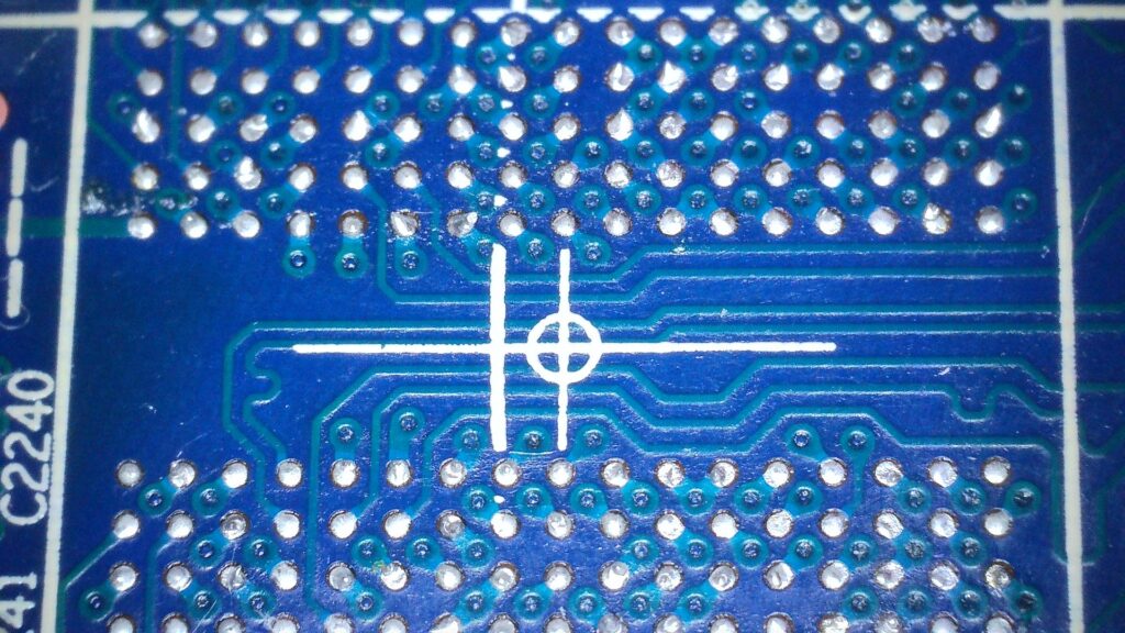
One problem with the ‘nudge test’ when re-soldering a chip is that it is quite possible to do it too early and mess up a partially soldered chip. Another option, which I am starting to prefer, is to ‘very slightly’ misalign the placement of the replacement chip e.g.
Obviously, the misalignment must be such that the solder balls under the chip are still in enough contact with the pads to pull the chip perfectly straight on re-flow e.g.
As you can see, those balls know exactly where they belong when re-flowed and you know the chip is back in place!
The replacement Procedure
1. Chip Removal
No preheater? – This procedure assumes you have a PCB pre-heater. If you don’t, my approach would be to use the hot air nozzle to slowly manually pre-heat the board and especially the area around the VRAM chip by working the nozzle about from a slight distance e.g. 10cm for say 30 seconds. This should heat reduce thermal stress (e.g. expansion of one specific PCB area) and possibly aid removal. Note, this is just as an idea, the actual timing and heat will vary with PCB size and may not even be necessary for smaller boards.
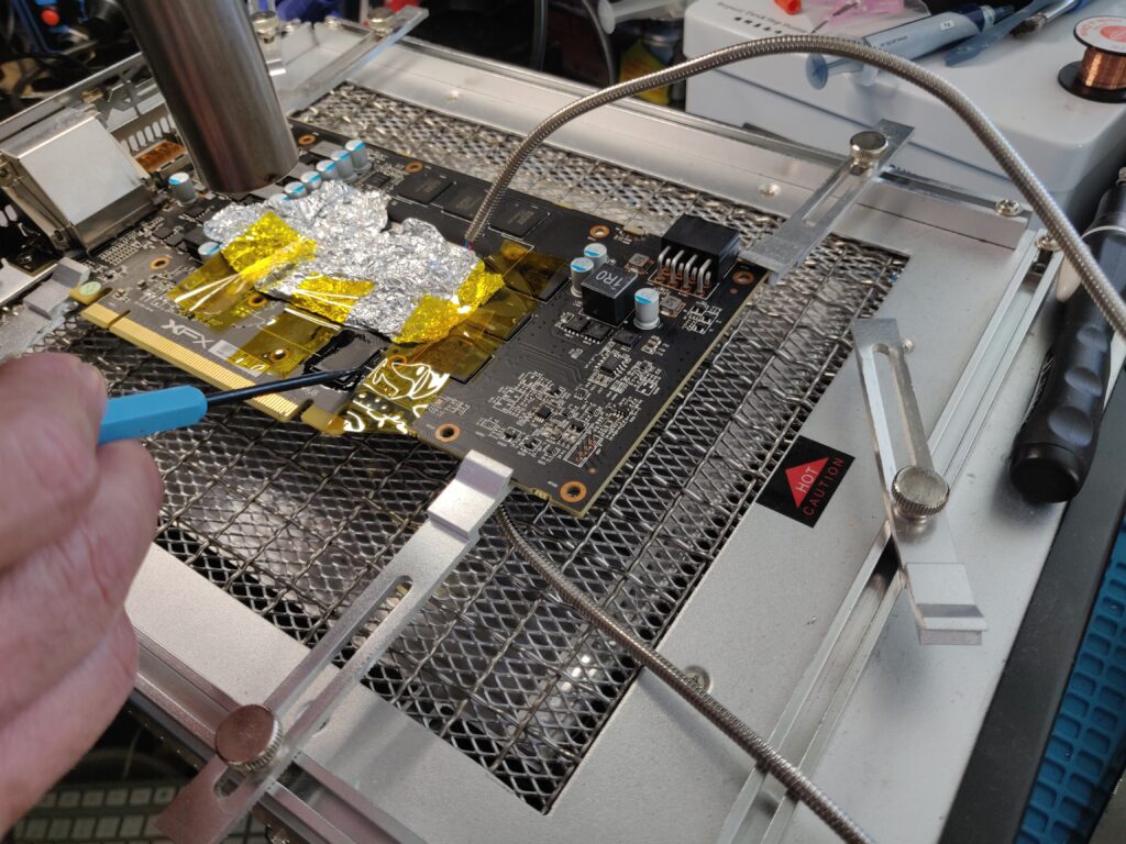
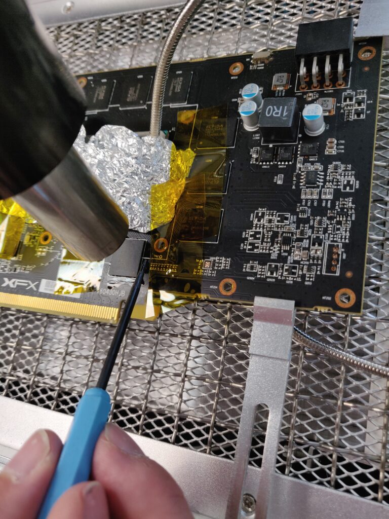
- Preheat the board to about 130-150 underneath and 110+ on the surface (can vary a bit) and cover any sensitive components with Kapton tape or kitchen foil.
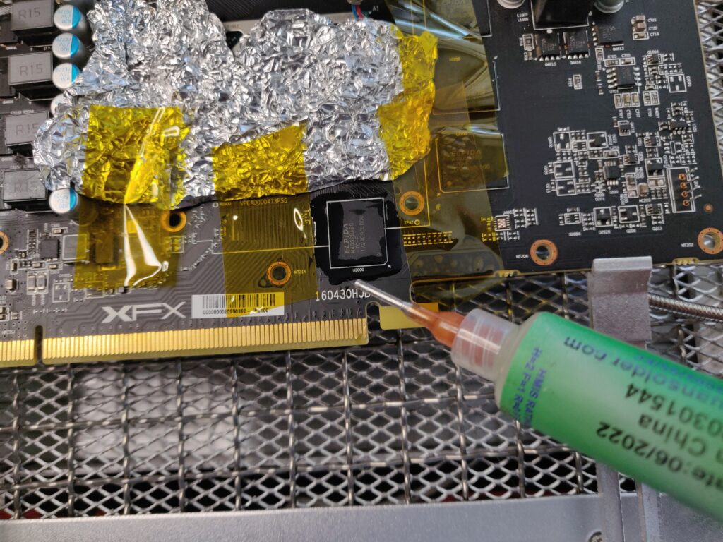
- Apply flux around the chip (optional)
- Begin to slowly heat with hot air station set to 375-425 deg C depending on the side of the PCB, max 450 (very large PCBs, very stubborn chips or perhaps without preheater)
- Try to raise the temperature over say 30 seconds to 250+, the flux should start to bubble
- Then close in and keep heating until it’s possible to slightly nudge the chip easily from the side
- remove chip with the suction tool or tweezers – be careful not to dislodge any nearby capacitors or resistors!
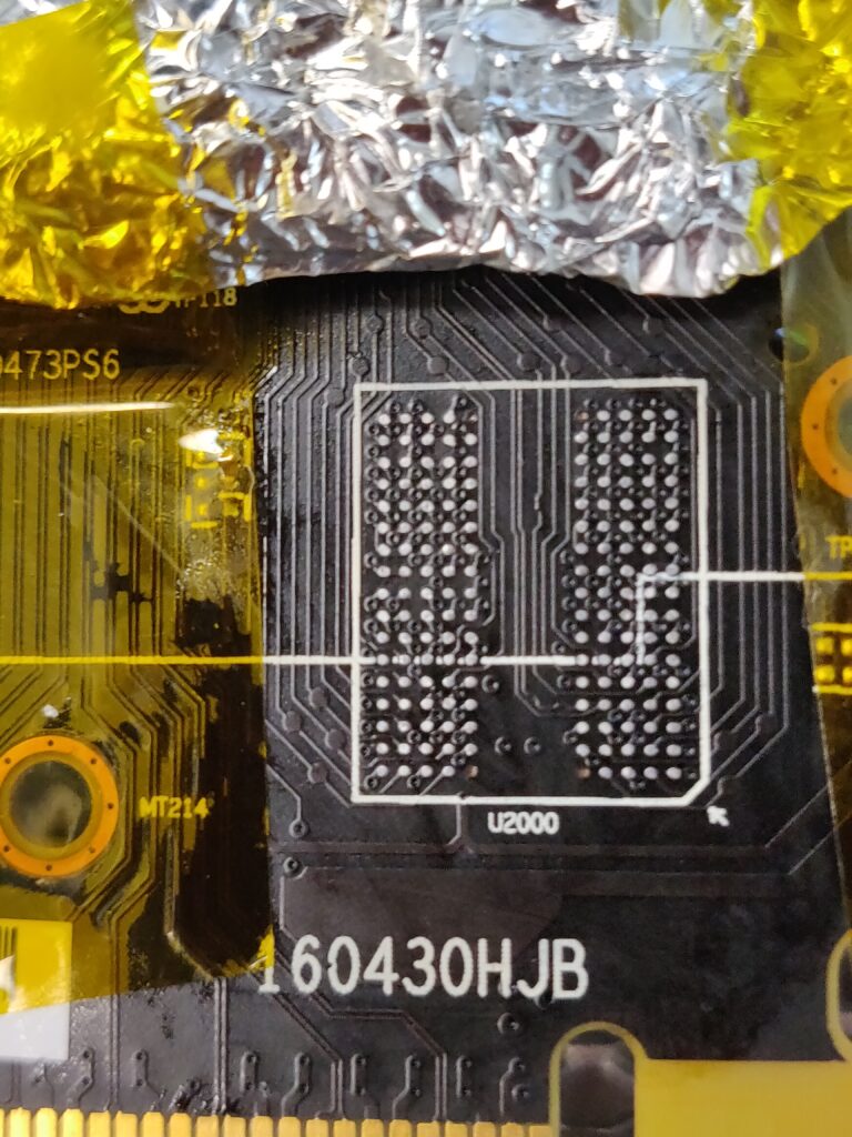
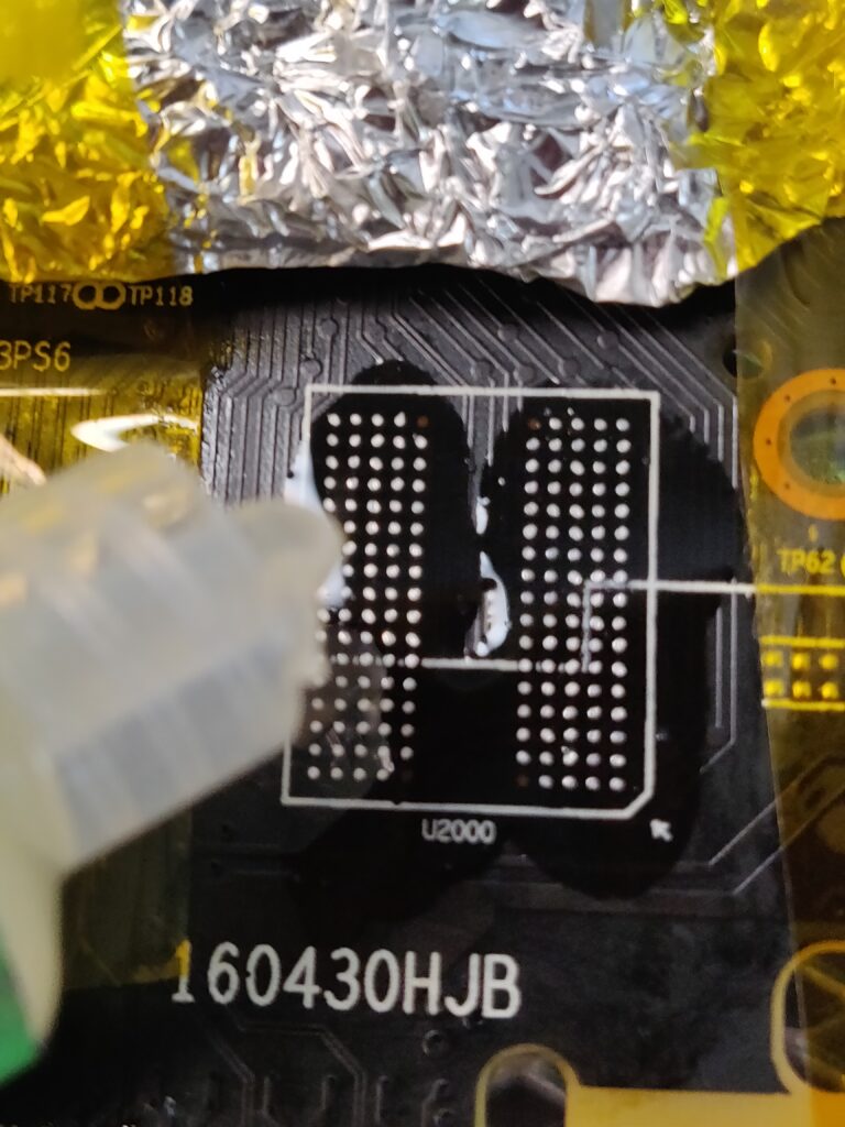
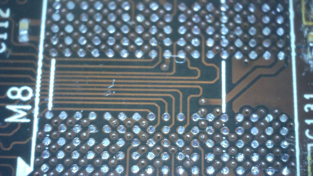
2. Pad Cleaning
- With the board still on the preheater and a BC3 soldering iron at 300, add more flux and run the soldering iron gently across the pads and wick gently to get the worst of the solder off
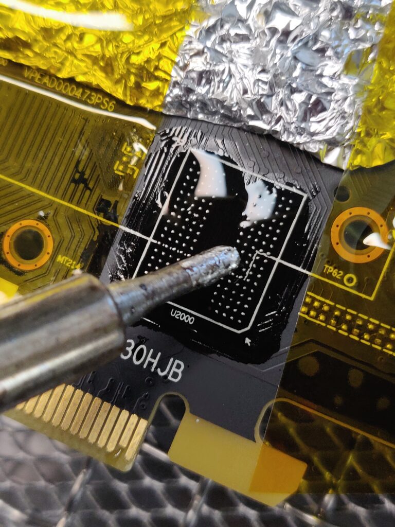
- Add some leaded solder to the iron tip and gently ‘float’ the solder iron tip across the pads. Cleaning the tip off in between sides.
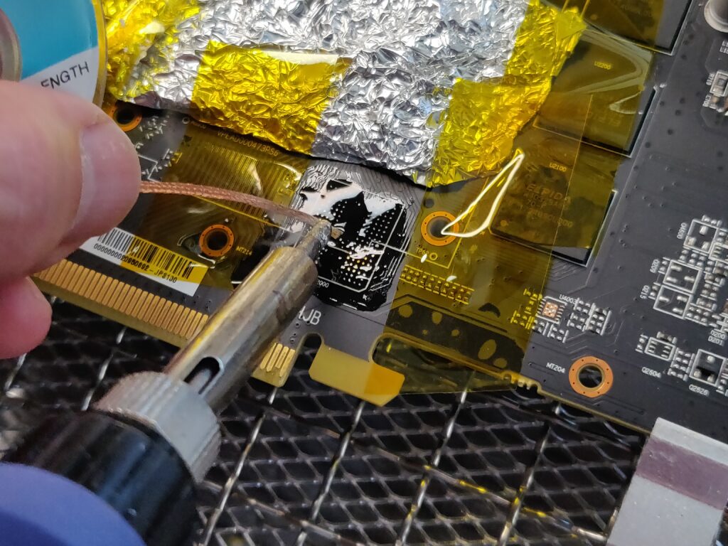
- Carefully wick away as much solder from the pads as possible (be careful with wider wick not to let it stick and potentially rip off pads).
- (Optional if you like to clean first) With card still on the preheater, clean area with IPA using a cotton-bud
- Ideally, you need the pads as clean and free of solder as possible. If they aren’t it may still be fine, but it could possibly increase the risk of excess solder causing ‘solder bridges’ and possibly shorts.
3. Chip Replacement
- Preheat board as in chip removal above.
- Add a thin layer of flux to the pads.
- Try to align the chip as well as possible.
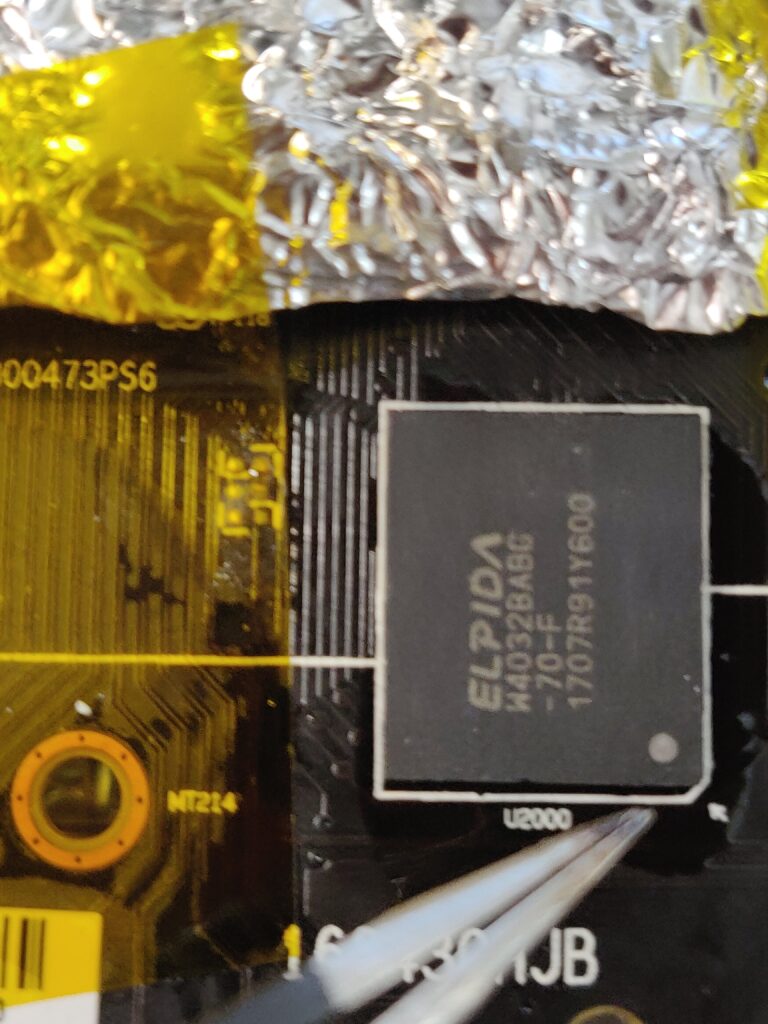
- Slowly heat as with chip removal.
- Set the hot air station to 375-400 deg C (depending on PCB size mainly) and close in until the chip settles down and repeat the same gentle ‘nudge test’ as in removal.
- (optionally) clean up any flux residue, a lot easier whilst the board is hot.
- Allow the board to cool before testing.
4. Testing
- (before powering on) When cool, check the resistance of the Vmem rail is normal. If shorted, the replacement procedure can be repeated (see common issues). If too high (like very high for memory), then it could be not enough was applied or uneven heat resulting in the chip not being fully soldered, you can reflow in this case.
- Power on test, if any usable picture is shown (may have artefacts), power down and replace the cooler before further testing.
- Consider retesting with mats or tserver.
- If all is well, proceed to windows and continue to stress-test etc for validating the fix.
Common Issues
These are issues that I have personally experienced.
- Short on VMem rail – One or more pairs of solder balls may have likely joined, possibly there was too much old solder left on the pads after cleaning (see HD 7850 – Attempt 1). Possibly too much flux might increase the risk of this. The replacement must be repeated.
- MATS errors on every bit – If this wasn’t the case before replacement, the chip may not be soldered down correctly (e.g. insufficient heat/reflow of solder balls). Example GIGABYTE GTX 1050TI 4GB Card B. A successful reflow may fix this.
- Artefacts – If there were previously no artefacts, then this can be a sign of one or more loose solder joints. A possible cause might be that not enough heat was used to get all solder balls correctly soldered. A successful reflow may fix this.
- Exact same MATS errors after successful replacement – memory controller faults, faulty connections under the GPU core and broken tracks can also cause MATS/memory errors. This needs more discussion and examples, but this may be identifiable from the patterns and exact errors in MATS with experience. Resolving this is likely beyond this procedure.
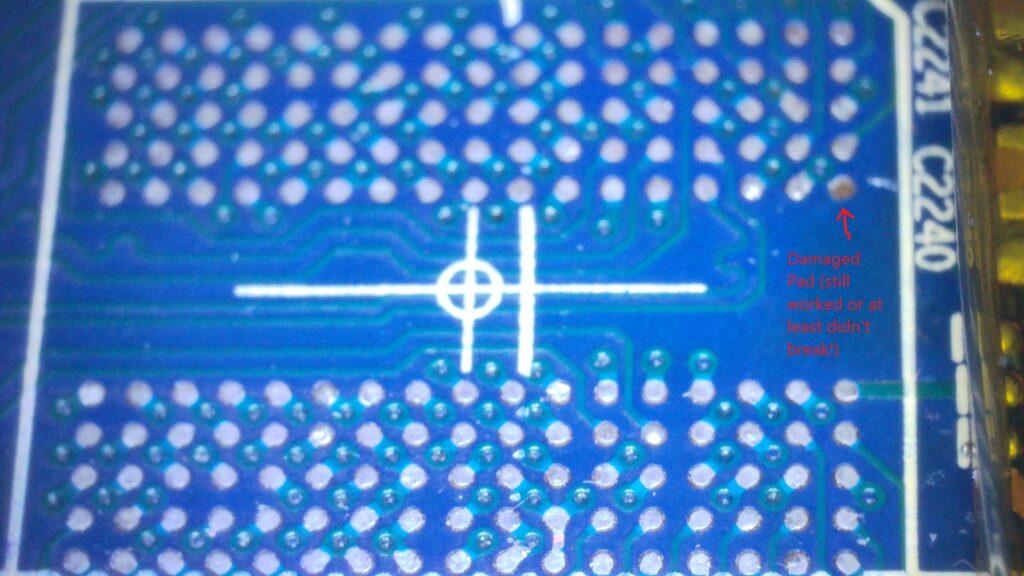
- Damaged or missing pads – After chip removal, sometimes pads will be damaged or missing. This doesn’t always indicate a problem, as certain types of VRAM chip can have pads that are not connected (normally the pads in the corners) – for example, see XFX RX580 8Gb (Card A). However, essential pads can be damaged before or during chip removal and cleaning, in this case, they must be repaired (TODO add separate guide on VRAM pad repair)
Samples & Results (cases where there were issues)
These were some of my first attempts, when I look back now, my pad cleaning skills were relatively poor and I had issues as a consequence e.g. ripped pads from solder braid sticking, shorts from too much old solder being left on the pads before replacement. Hopefully, these examples can help others from repeating my mistakes.
Links to example cards (successful fixes)
Here you can take a look at some examples of cards that have been through the above process.
- Sapphire HD 7850 2Gb (successful replacement, probably luck, as it was my first one)
- MSI GTX 770 2GB (2048 MB) Twin Frozr (A) (Initial reflow failed, eventual chip replacement for a hopefully long-lasting fix)
- MSI GTX 770 2GB (2048 MB) Twin Frozr (B) (similar to card A above, the initial reflow failed and the chip needed replacing. These cards helped teach me that reflows should not be considered ‘permanent fixes’)
- Zotac GTX 1060 6gb (initially a successful VRAM replacement, then the card developed memory errors again after stress. Suspected core BGA issues, I plan to re-ball the core on this card when I get equipment and a chance)
- MSI GTX 1050 2Gb (various self-inflicted issues, a good one to look at for some examples of mistakes! 🙂 Ended up re-balling the chip for this one – successful)
- GIGABYTE GTX 1050TI 4GB Card B (successful replacement, one of my best ones so far)
- MSI GTX 1060 3Gb (successful replacement, apart from some capacitors that I accidentally dislodged!)
- XFX RX580 8Gb (Card A)
- https://rupz.me/electronics/gtx-titan-black-repair/ (gtx Titan black with 2 shorted vram chips replaced to fix)
Interesting. Must try on my broken 780Ti sometime.
Thanks for the comment Andre. Please do ask if you need any help with your 780 ti – here is an example that I fixed recently https://rupz.me/electronics/gigabyte-gtx-780-ti-windforce-3x-card-c/
I’m planning on buying a preheater soon, but I’m surprised to see you still require such high hot air temps while using one. That isn’t what I’ve seen with others using them, so maybe the preheater isn’t putting enough heat into the board? Which one do you have, 853?
Hi James, thanks for your comment. I like to use a preheater, but others do it successfully with just hot air. Things to consider:
-I use a Quick 857DW+ which I am very happy with, but there are more powerful stations.
-The temperature required is strongly influenced by the PCB type/size, I find larger cards e.g. 7 series boards, typically take a lot more.
-I am often only preheating to about 100 deg C, you could go to 120 deg C and probably cut down the hot air.
-The time to remove is also a factor, like you could probably use 350 deg C hot air, but take longer. I am not sure the exact trade-offs, but I don’t like to heat chips for too long.
Hope this helps. Thanks. Rupert
Hi,
why do you use leader solder?
Isn’t the stuff on the PCB leadfree? Wouldn’t that cause a bad mixture/contact if you use leaded solder.
Hi Mat, thanks for the question, I am used to using leaded solder to clean pads and remove old lead-free solder, because it mixes and lowers the melting point of the lead-free solder residue. I find it helps the cleaning process and I try to wick the pads a best as I can without leaving the mixed solder.
It is true that all the original solder on the PCB is lead-free, but I think many repairers find leaded solder easier to work with. I might label that step as optional, as you could simply wick away the old solder, I might try that. Also, lowering the heat required during pad cleaning might help reduce the risk of damaging the pads? Again, good to hear what others think. Please let me know if you’ve had any issues too, and maybe we can improve the process to help others.
Thanks,
Rupert
I’m having issues trying to find the correct memory for this laptop (MSI GL66 Pulse UGKV), I found that B1 was having write issues (600k+). I read the chips and this is what it said “Samsung 110 K4Z80325BC HC14”. I’ve found many chips that have the “K4Z80325BC HC14” part but not the 110. What do these numbers mean, and would a chip with a different number than 100 work?
Hi, I haven’t worked on laptop memory issues, but if the K4Z80325BC HC14 matches, then I would expect it’s fine. Sometimes there is a batch or date number, but it shouldn’t matter. To double check, you could read the Samsung memory data sheet, as it normally explains the markings.i would expect the chips you found will work.
When you say “ Try to raise the temperature over say 30 seconds to 250+” are you talking about the pre heater or the soldering iron?
Hi, I used to try and follow the solder melt temerature profile which involves a slow steady climb in temperature etc (a bit like it says here https://www.nxp.com/docs/en/application-note/AN3300.pdf). I don’t really do this anymore, I tend to just work the hot air around the chip until I can see the solder is following e.g. nudge the chip a tiny bit.
Hey so i succesfully replaced the vram on a 2080 super and the errors stayed the same. Any advice?
Hi, sometimes the type of error in MATS can give a hint, but if only 1 chip shows some errors, quick thoughts would be that potentially some of the solder connections under the core could be an issue or the traces between – sometimes this can be seen as different resistances measured on the VRAM chip’s pads. If errors are shown on all bits, then potentially one or more of the minor components round the edge of the VRAM chip could be faulty/damaged e.g. resistor/capacitor. Another unfortunate possibility is that the memory controller in the core is faulty for that VRAM chip, not really fixable. I would also consider asking on the LER discoord, hope you get it fixed. Thanks, Rupert
Hey there! I’ve been following your blog for a while now and finally got the bravery to go ahead and give you a
shout out from Dallas Texas! Just wanted to mention keep up the great work! https://menbehealth.wordpress.com/
I have fun with, lead to I found just what I used to be having a look for.
You have ended my four day lengthy hunt! God Bless you man. Have a nice day.
Bye