Seller Note “The graphics card is DEAD unresponsive. NOT powering up.”
Summary
- I bought this as I have another similar card with a short that I wanted to get some measurements for Gigabyte RX 460 2Gb. It appears to have the same fault, hopefully, it can still help.
- Resistances
- Vcore – 2Ω
- VMem – 58.2Ω
- VDCCI – 37.8Ω
- Display Rail – 32.9Ω
- 1.8V – 2.01KΩ
- 5V – 3.78KΩ
- 3.3V – 3.3KΩ
- 12V – measures about 1KΩ (slot), but this is false since the 12V fuse is blown. I would expect the true resistance to be higher
Investigating shorts on 12V rail
OK, if that 12V rail fuse is blown, let’s start there and measure the VCore high-side MOSFET gate resistances. Here we go, the top one Q512 has a low gate resistance of 5.6Ω, whereas the other three phase’s gates measure ~8KΩ. Let’s remove that MOSFET and see what happens to the 12V rail resistance.
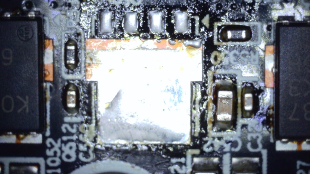
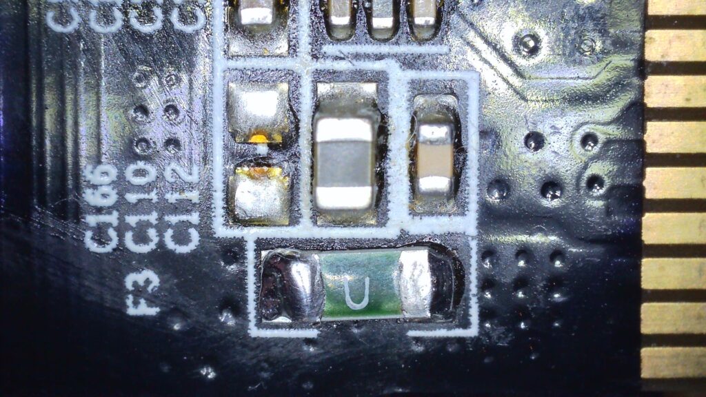
After the removal of Q512 and a new 10A fuse (F3), the 12V rail read a healthier 4.5KΩ. Testing with power, we have a BIOS picture, so the core hopefully isn’t completely dead!
What I don’t know yet is if the driver is also bad, replacing the MOSFET can sometimes end in disappointing smoke if there is an underlying issue. I will test the gate to see if there is a decent-looking waveform with an oscilloscope. Waveforms all look reasonable across all 4 phases.
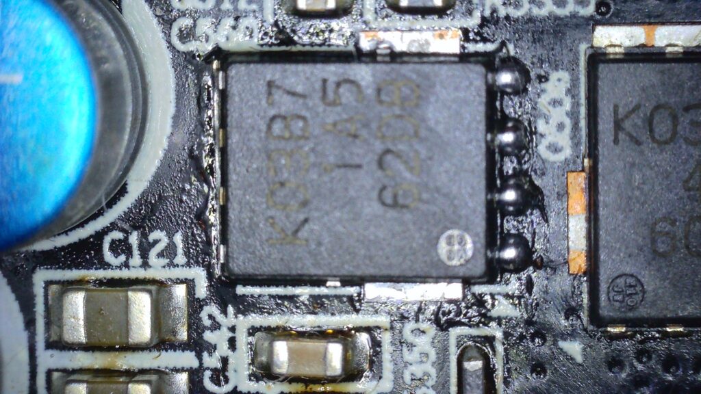
I need to buy some K03B7 high-side MOSFETs, unless I can find a donor card.
Update – Working and needs more testing
After replacing the faulty MOSFET, the card seems to be working and all 4 phases are showing the same waveform on an oscilloscope, so hopefully, it’s in good shape! 🙂
Next steps
- These little RX 460s are really just desktop cards, not designed for any real kind of gaming.
- I noticed that the fans cut in quite late and whilst the core remains at a low temperature under full load, the VRM area at the back of the card feels hot.
- Will continue to test and maybe take a look with a thermal camera to make sure no components appear strangely hot.
- There may be space to fit a stick-on heatsink to the VRM MOSFETs. Having worked on two identical cards each with a blown MOSFET, I am guessing the VRM area is a weakness on this model and a bit of extra heat dissipation might help.
Update 05/08/2023 – Failed testing, now missing VDCCI, VMem and VCore voltage rails
It’s been a long time since I looked at this card, but I remember it failing testing and me putting it to one side. I have now taken another look at the card months down the line. Learnings:
- Write down test findings at the time and don’t assume things, take measurements!
- This card is now missing voltage rails, I didn’t suspect this at the time of failure. This means I need to investigate the circuitry from Display Rail upwards, as PEX, 1.8v and 5v all look fine.
- When repairing shorts, don’t cut corners! I have tended to try and get away with simply replacing the high-side MOSFET and testing. After time, I have realised that it is advisable to replace at least the driver and the high-side, probably the low sides too. In bad cases the PWM controller might also need replacing.
Maybe there was an underlying fault in the VCore circuitry, VDCCI is also under the same PWM controller. Normally on polaris type cards we have this kind of voltage rail sequence:
5V→ 1.8V→ Display Rail → VMem/VDDCI → VCore
Luckily, this card has a schematic avaialble. A quick look makes me think that VMem enables both VDCCI and VCore on this model, because VDCCI and VCore use the same controller, which in turn is enabled by VMem.
VDCCI and VCore PWM is an NCP81022 https://media.digikey.com/pdf/Data%20Sheets/ON%20Semiconductor%20PDFs/NCP81022.pdf
VMem controller RT8120 https://www.richtek.com/en/Products/Switching%20Regulators/Single-Phase%20Step-Down%20Controller/RT8120.aspx