Summary
- Nice 4Gb version, was missing a screw and came in a beat-up box, but cheap!
- Resistances
- Vcore – 5.7Ω (rising to 7.6Ω after the shorted MOSFET was removed)
- Vmem – 100Ω (Samsung)
- 5V – 507.6Ω
- 3.3V – 1.58KΩ
- 12V PCI – 2.8KΩ, PCI-E – 5.7Ω!
- Has a clear 12V PCI-E short, plus terrible burns to the resistors bridging the 12V power planes on the PCB
- Have identified and removed the shorted 12V MOSFET on the VCore VRM
- Have cleaned the burned resistors away and replaced them with a 15A fuse.
- The card has a clear picture and loads drivers
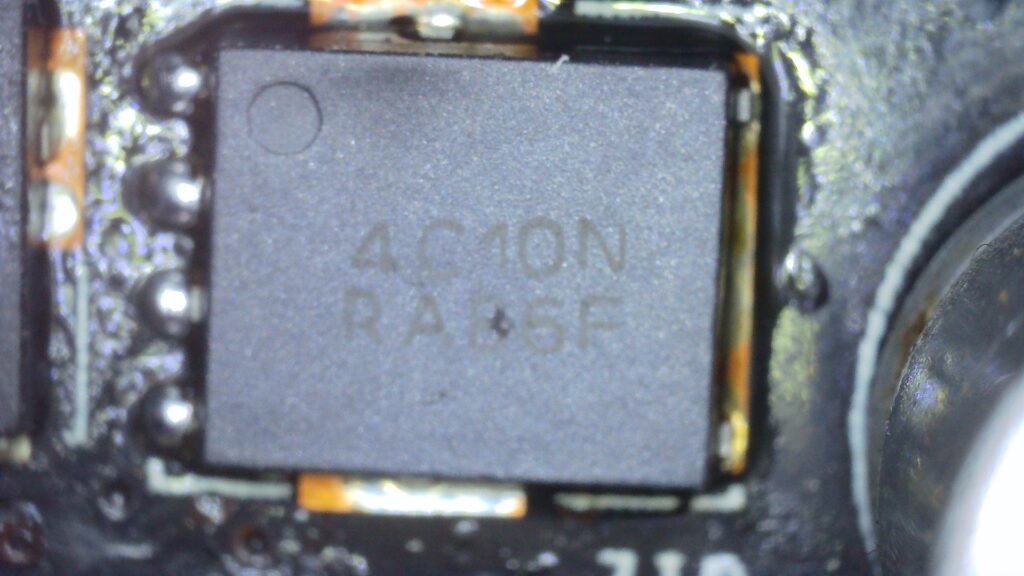
- Waiting for a replacement 4C10N MOSFET
Investigating the 12V short and burned components…
Measuring the VCore high-side gates, all read 7.98KΩ (normal), apart from Q12 which reads 50.3Ω (suspect!)
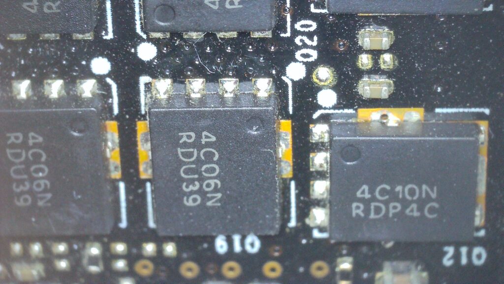
Removing Q12 clears the 12V short, the 12V rail resistance rises to ~8MΩ and the VCore resistance rises to 7.6Ω – good. Some burned components to deal with:
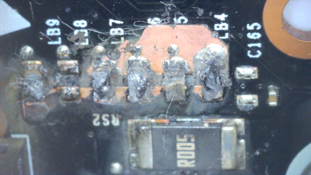
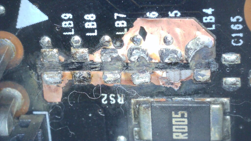
After grinding away the burnt resistors, the damage is not too bad. The burned components are actually just 6 x 0Ω resistors, I don’t have any and preferred to replace them with a suitable 15A fuse.
Update 26/02/2023 – Replacing MOSFET and driver
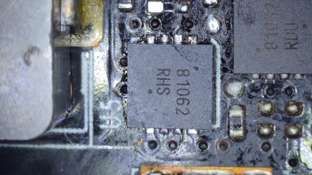
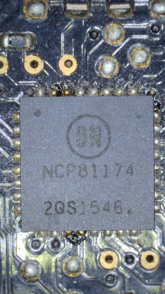
After replacing the shorted high-side MOSFET, the gate resistance measured a consistent 7.95KΩ like the others. However, it blew immediately after trying to test the card. So we can try replacing the associated driver. It is a 81062 https://www.onsemi.com/pdf/datasheet/ncp81062-d.pdf
After the replacement, the good news is that the card starts (without smoke!), but I can see that phase 4 is not working. Assuming all chips are good and soldered fine, we need to start taking a look at the PWM signal to the driver:
We can see some nasty-looking flux deposits around the PWM. Measuring the gate PWM test points shows the gate 4 signal appears inverted compared to the other 3 working gates – interesting. Presumably, the PWM knows there is something wrong with phase 4 and is telling the driver to only switch on the low-side MOSFETS? (think this is what the driver datasheet suggests). Next, I would like to check the current sense pins for all the phases.
TODO When card is fully working, apply solder mask