Seller Note “When installed in pc the fan spins but with no output to the screen unfortunately otherwise in great condition”
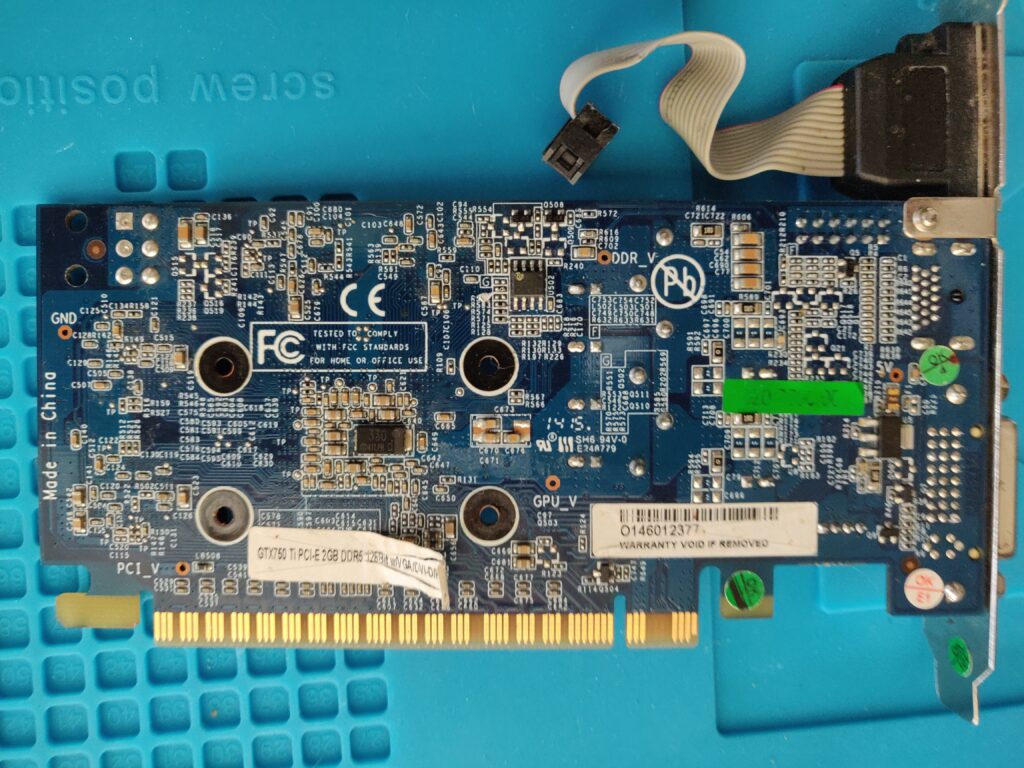
Pre Checks / Multimeter Only
| Test / Checks | Result | Notes |
|---|---|---|
| 1. Visual Inspection Eye / Magnifying Glass | OK | No missing components, but a bit dirty. |
| 2. Visual Inspection Microscope | – | |
| 3. Check for shorts on 12v PCI, 12v PCI-E, 3.3v | OK | Couldn’t find any obvious shorts. |
| 4a. Resistance VCore (~0.5) | Ω | |
| 4b. Resistance VMem (~60Ω) | Ω | |
| 4c. Resistance 3.3v Rail (~960Ω+) | Ω | |
| 4d. Resistance 5v Rail (~5KΩ) | K Ω | |
| 4e. Resistance 1v PEX Rail (~123Ω+) | Ω | |
| 4f. Resistance 12v BUS (14.7kΩ ) | KΩ | |
| 4g. Resistance 8.8v Rail (18.7KΩ ) | KΩ |
Power On / Test Rig Checks
| Tests / Checks | Result | Notes |
|---|---|---|
| 1. Observations (e.g. PCB heat noticed, blank screen, power light on monitor, bios screen, o/s loaded, artefacts, ) | No display (no light on monitor) Fan spins, GPU never gets warm (no power). Some warmth in the VRM area. | No power to CPU. |
| 2. Voltage VCore (~0.88v) | 0.914v | OK |
| 3. Voltage VMem (~1.4v) | ~0v (4.3mV) | !!! Need to investigate further |
| 4. Voltage PEX Rail (~1v) | ? | !!! |
| 5. Voltage 3.3 BUS | 3.3v | present |
| 6. Voltage 12 Ext | 12v | present |
| 6. Voltage 5v Rail | 5v | present |
| 7. Voltage 8.8v Rail | – | – |
That memory area needs further investigation, access is a bit hard with the cooler in place. The board is quite small and the heatsink is quite large and gets in the way of diagnostics. I will see if it can be run with a make-shift heat sink. Alternatively, I will try and rig up a lab power supply to a riser.
Next Steps
Actually, there is no need for a heatsink, as the GPU remains cold. There is some warmth towards the IO shield / VRM area, but hard to pinpoint. Still cannot find any trace of the 1v PEX rail. I am guessing VMem is missing perhaps because PEX is also missing. Hopefully, there is a chance that the core and memory are ok and there is some failed power switching/delivery component. Interesting!
Deep Dive
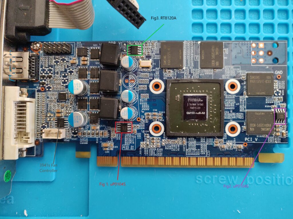
Used my cheaper microscope to take a closer look at the PCB, in particular, components relating to possible minor voltage production (VMem 1.5v, PEX 1v). Found two Low Dropout Regulars to investigate (refer to Fig 1 & 2 in photo above for positions) :
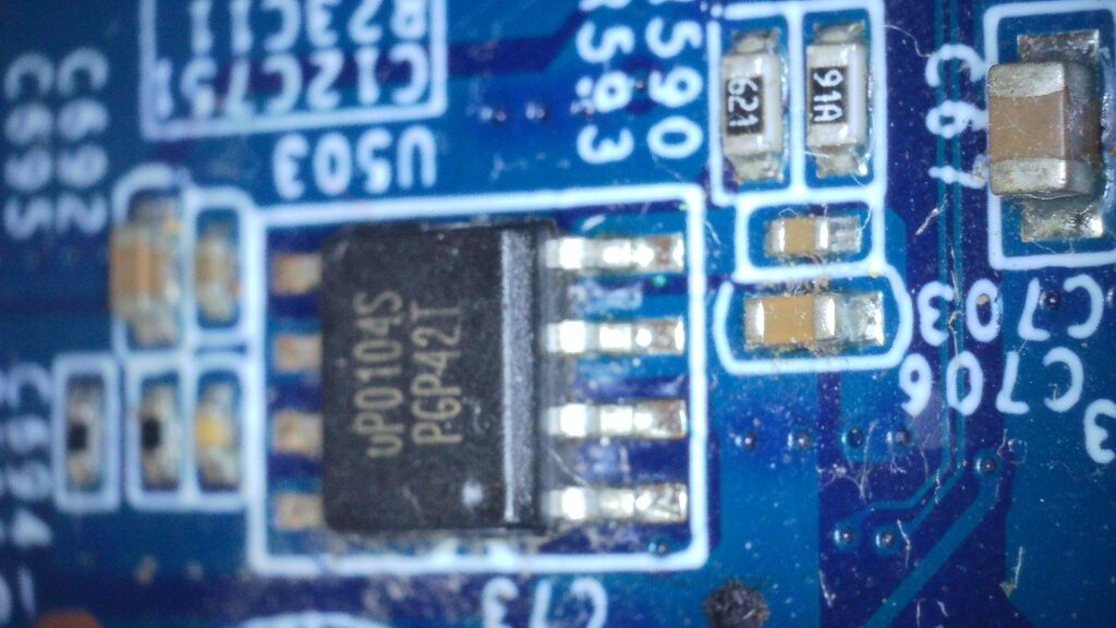
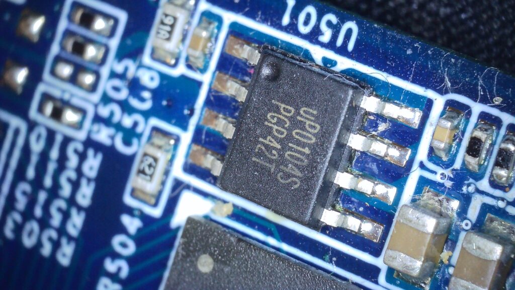
I struggled to find a datasheet for these exact components, but I did find this seemingly very helpful image from a Russian site:
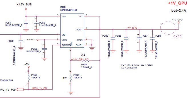
Also here is a link for a similar chip http://images.100y.com.tw/pdf_file/38-RISHTEK-RT9018.pdf
Time to check voltages on these chips:
| PIN | Expected V | Actual V |
|---|---|---|
| 1. PGOOD (Dot) | From vCore? | 0v Missing |
| 2. EN | 2v+ ? | 3.07v OK? |
| 3. VIN | 3.3v | 0v Missing |
| 4. VDD | 5v | 5v OK |
| 6. VOUT | 1v | 0v Missing |
| PIN | Expected V | Actual V |
|---|---|---|
| 1. PGOOD (Dot) | From vCore? | 0v |
| 2. EN | 2v+ ? | 5v OK? |
| 3. VIN | 3.3v | 0v Missing |
| 4. VDD | 5v | 5v OK |
| 6. VOUT | 1v | 0v Missing |
Seems we could have a problem with the 3.3v rail.
TODO Test resistor R649
Want to understand more about the Vmem rail.
RT8120A http://www.chipset-ic.com/datasheet/RT8120A.pdf (single-phase synchronous buck PWM DC/DC controller designed to drive two N-MOSFET) I am guessing this drives the two MOSFETs in the memory VRM.
Also, there is a chip marked 0T=1C 622 which I think is a PWM used to drive the Vcore VRM http://www.smdcode.net/uploads/Files/Datasheet/0T/RT8811A.pdf
Update: Unfortunately, I accidentally shorted to of the Vcore mosfet pins whilst measuring with my new meeter, smoke seen and now no VCore – dam it! The driver appears to have a burn mark on it, would imagine at least the driver and the mosfet need replacing. This is now long fix territory, as I need to find replacements and hope for the best in terms of no further collateral damage.
Update 29/07/2022 – Have a working identical card to validate most of the above
I now have a working identical GTX 750 ti and many months more experience, so thought it could be a good time to revisit and correct some of my initial findings.
Working card resistances
- VCore – 9.5Ω (This card 10.5Ω)
- VMem – 43.9Ω (This card 41.6Ω)
- PEX – 319Ω (This card 329Ω)
- 5V – 508Ω (This card 509Ω)
- 3.3V – 7.5KΩ (seems relatively high, but similar on this card 7.6KΩ)
- 12V – 637Ω (This card 440Ω)
So all the resistances look fine.
Working card voltages
- VCore – 0.97V (This 0V card)
- Vmem – 1.52V (This 0V card)
- PEX – 1.05V (This 0V card)
- 5V – 5.15V (This 5.11V card)
- 3.3V – ok (This card – ok)
- 12V – ok (This card -ok)
Well, I know I fried the VCore PWM. Originally there was VCore, but I am not sure if PEX was ever there (how I missed the marked measure points shows my complete lack of experience then). PEX and VMem may be dependent on VCore, probably the way forward is to consider:
- Buying another RT8811A VCore PWM and replace it
- Buying another RT8120A, not proved, could be why VMem was never present
- To be on the safe side, buy some uP0104S (can see now that u501 is PEX, might just need enable)
- And possibly some MDU1514, MDU1516 MOSFETs
- Probably not worth the investment in all those parts I might not need, but I would really like to fix this card as it is one of my first projects.
- Will also take a look in my donor card collection. Ah ha!, I already bought some RT8811A for a GTX780! Will give that a try 🙂
OK, to the VCore PWM replacement appears to be successful:
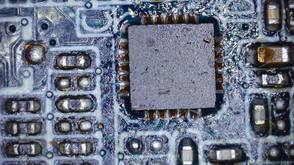
It appears to be working as we have 0.9V on VCore, as we did before I shorted the controller. Very little heat on the core though. Now we need to work out what happened to VMem and PEX.
U501 (uP0104S) – PEX
| PIN | Working Card | This Card |
|---|---|---|
| 1. pgood?(Dot) | 0.95V? | 0V |
| 2. ? | 5V | 5V |
| 3. ? | 1.5V | 0.01 |
| 4. VDD? | 5V | 5V |
| 5. GND? | 0V | 0 |
| 6. FB? | 0.8V | 0 |
| 7. VOUT | 1.04V | 0 |
| 8. GND | 0V | 0 |
U503 (uP0104S) – I don’t know what this rail is?
| PIN | Working Card | This Card |
|---|---|---|
| 1. PGOOD (Dot) | 0.1V? | 0v |
| 2. ? | 3V | 3.09 |
| 3. ? | 1.5V Vmem? | 0v |
| 4. VDD | 5V | 5V |
| 5. | 0.01V | 0v |
| 6. | 1.06V peX? | 0v |
| 7.VOUT | 0.8V | 0.01V |
| 8. GND | 0V | 0v |
U504 (RT8120A) – VMem Rail
| PIN | Working Card | This Card |
|---|---|---|
| 1. BOOT | 13V? | 1.36 |
| 2. UGATE | – | Oscilloscope: nothing on this |
| 3. GND | – | – |
| 4. LGATE | – | Oscilloscope: Has waveform |
| 5. VCC | 12V | 12V |
| 6. FB | 0.6V | 0.01 |
| 7. COMP/EN | 0.97V | 1.13 |
| 8. PHASE | – | – |
OK, this was quite painful to measure without any cooler, the core gets hots very quickly. Since there is VCC and EN are present, I would suspect the U504 Vmem PWM controller is faulty. A further indication of this is that the UGATE pin shows no signal and the LGATE has a signal, the net result would be 0v.
So, I think I need to either buy or find a RT8120A. Then, hopefully its a case of:
5V -> VCore (resolved) -> VMem (needs fix) -> PEX
Ah ha! I have found two donor cards with a RT8120A 🙂
TODO Add picture of replaced VMem PWM
Well, there’s some improvement in that there is some VMem (~0.6V) and some PEX (~0.4V), but those aren’t high enough. Strange to have partial voltage. Need to dig deeper, maybe the feedback curuit isn’t working right? Strange PEX Is also low..
I have to imagine there is something disfunctional about the VMem VRM, the PWM gets pretty hot (it was from a very old donor board). I would also say the single VRM capacitor seems hotter than I would expect. Maybe it is faulty and that could have lead to the original issue? I should next try replacing the capacitor.
I have replaced the capacitor, but things have not improved. Possibly that memory VRM is faulty the donor board it came from was in quite bad shape.