Seller Note “Was working fine until I turned the PC on one day and there was no power going to it.”
Summary
- Visually seems ok, couldn’t see any missing components. A bit dirty in places.
- Check fuse F1800, F400 (top left) – Both seem fine.
- Resistances seems OK. Main voltages present, but missing Vcore and Vmem at least.
- Need to deep dive on buck converters etc to try and understand power rail logic (no boardview available)
- Don’t think COMP is high enough on the Vmem drivers U701 & U801 – Need to understand more
- Need to check U601 PWM for Vcore
Pre Checks / Multimeter Only
| Test / Checks | Result | Notes |
|---|---|---|
| 1. Visual Inspection Eye / Magnifying Glass | A bit dirty in places. Nothing obviously missing. | |
| 2. Visual Inspection Microscope | Found two fuses, think both are OK. | |
| 3. Check for shorts on 12v PCI, 12v PCI-E, 3.3v | OK | Couldn’t find any obvious shorts. |
| 4a. Resistance VCore (~0.5) | 4.6Ω | |
| 4b. Resistance VMem (~60Ω) | 40Ω+ | |
| 4c. Resistance 3.3v Rail (~960Ω+) | 420Ω | |
| 4d. Resistance 5v Rail (~5KΩ) | 1.7KΩ | |
| 4e. Resistance 1v PEX Rail (~123Ω+) | 88.5Ω | |
| 4f. Resistance 12v BUS (14.7kΩ ) | 1.8KΩ | |
| 4g. VDDCI | 40Ω+ |
Power On / Test Rig Checks
| Tests / Checks | Result | Notes |
|---|---|---|
| 1. Observations (e.g. PCB heat noticed, blank screen, power light on monitor, bios screen, o/s loaded, artefacts, ) | Few voltages. No picture. No heat (GPU). | |
| 2. Voltage VCore (~0.88v) | 0v | Missing |
| 3. Voltage VMem (~1.4v) | 0v | Missing |
| 4. Voltage PEX Rail (~1v) | 1.0v | L900 |
| 5. Voltage 3.3 BUS | 3.3v (F1800) | |
| 6. Voltage 12 Ext | 12v | |
| 7. Voltage 5v Rail | 5v (F400) | |
| 8. Voltage VDDCI | 0v | Missing |
| 9. Voltage 1.8v | 1.8v | LDR U300 (back) |
Deep Dive Buck Converters & LDRs
Vram VRMs U701 & U801
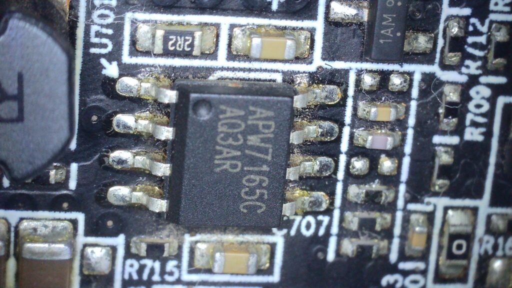
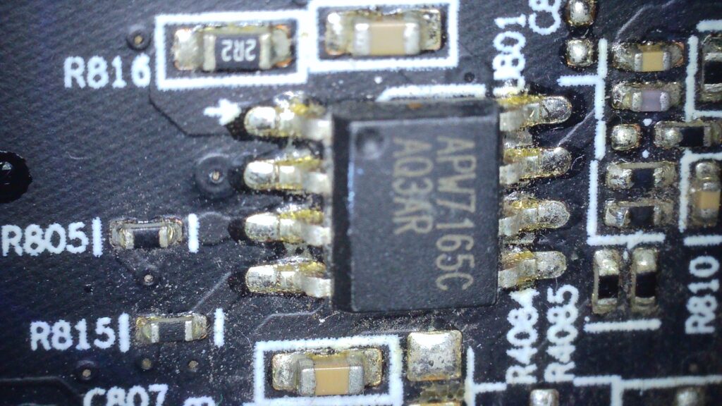
Both are APW7165C https://datasheetspdf.com/pdf-file/971451/AnpecElectronicsCoropration/APW7165C/1 these appear to drive the Vram and VDDCI MOSFETS.
Check pins 1 (BOOT) and pin 5 (VCC)
U701 Pins
- 1 BOOT -> 12v
- 5 VCC -> 12v
- 7 COMP -> 0.4 (<0.6 disable)
U801 Pins
- 1 BOOT -> 11.69v
- 5 VCC -> 12v
- 7 COMP -> 0.4 (<0.6 disable)
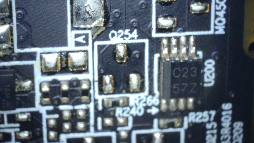
I don’t actually know what C23 57Z is.
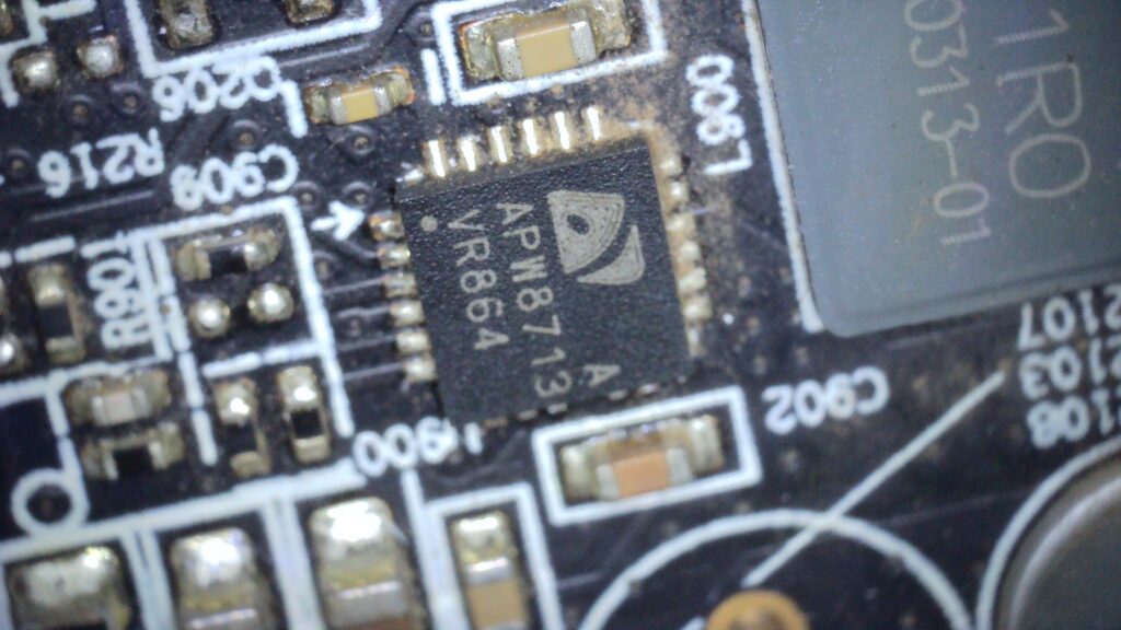
PWM APW8713A https://datasheetspdf.com/pdf-file/1091961/ANPEC/APW8713A/1
L900 is PEX, measuring healthy 1.0v
Check pins:
- 1 POK -> 3.3v
- 2 EN -> 5v
- 20 BOOT
- 8,9,22 VIN
- 21 LDO
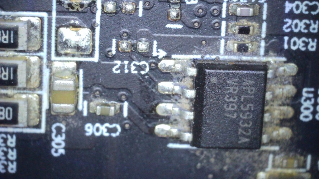
This is an LDR https://datasheet.lcsc.com/lcsc/1912111437_Anpec-Elec-APL5932AKAI-TRG_C351167.pdf
Check Pins:
- 1 POK -> 0.9v
- 2 EN -> 3.3v
- 3 VIN -> 3.3v
- 6 VOUT -> 1.8v
Looks healthy. This is the 1.8v source.
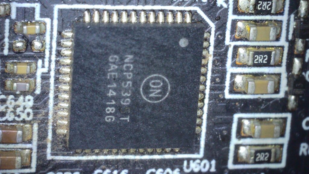
This is the PWM for the 3 phase Vcore VRM https://www.onsemi.com/pdf/datasheet/ncp5395t-d.pdf
Pins to check:
- 23 12VMON -> 1.3V ?
- 24 VCC -> 5v (ok)
- 33 EN -> 3.3 (ok)
- 34 VR_RDY -> 0.01 ?
- 40 VCCP -> 0.03 ?
- 23 12VMON -> measure
I’m not sure if this suggests an issue with the VCore PWM? Both VMem and VDCI controllers both look to be disabled by pulling their COMP (EN) pins low. I don’t know what order the voltages come on for an R9 370, but it could be that VCore enables VMem and VDCI.