Seller Note “When you boot it, it will turn on the display for about a minute before turning off.”
Summary
- Looks OK, was cheap, warranty sticker is still in-place. One really nice feature of some Asus cards is the labelled test points on the back of the card (nice one ASUS!).
- Resistances OK
- VCore – 1.6
- VMem – 286 (Micron D9SXD)
- PEX – 357
- 1.8V – 307
- 5V- 3.5K
- 3.3V – 4.7K
- 12V – 5K
- Seemingly a blank screen on driver load… However, this is not the common case or at least I’ve not seen it.
- MATS passes, so memory is hopefully OK – A common black screen with a back-light sometimes means a memory issue.
- As a second card, unusual behaviour can be observed regarding power delivery. When the HDMI is plugged into this card (rather than the primary), the screen blinks on/off and VRel and voltage matching voltage drops can be seen (see GPU-Z shots).
- The BIOS initially looked suspect, but eventually looked normal (see shots)
- Need to investigate the VCore VRM
Investigating Power Delivery
As a second card, using an oscilloscope to measure the 3 phases shows the same pattern on each. In a resting state, the waveform is relatively clean (about 0.6750V). However, when you load to the card by plugging in the HDMI lead, the output can be seen to switch between a rough/shimmering waveform with more waves in the drive state (which looks unstable, delivering 1.05V) and the cleaner resting state.
Update 02/10/2022 Investigating VRM
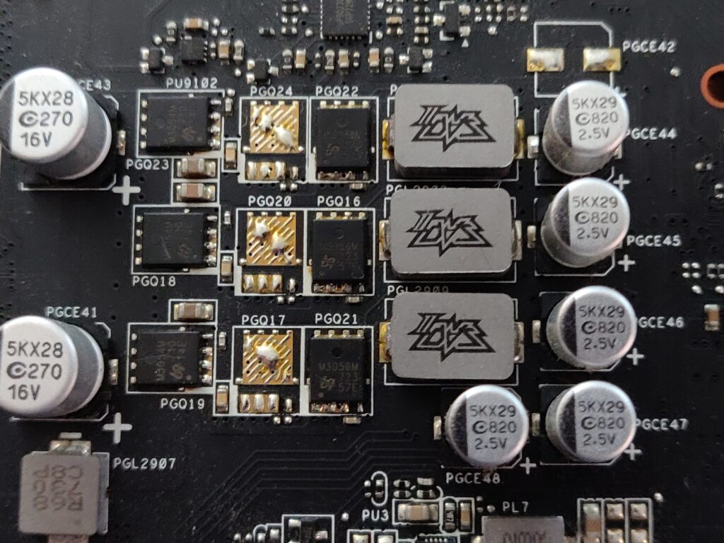
The PWM is uP9023q (TODO find datasheet, same as uP9501 ?)
The phases comprise of 1 high-side and 1 low-side MOSFET.
| Phase | Description |
|---|---|
| Phase 1 (bottom, nearest PCI slot) | HG1 goes to the PWM via a 0 Ohm resistor (check). Resistance measured at 7.3 MOhm LG1 goes to the PWM via a 13.7K Ohm resistor (check). Resistance measured at 13.74 K Ohm |
| Phase 2 (middle) | HG2 goes to the PWM via a 0 Ohm resistor (check). Resistance measured at 7.24 MOhm LG2 goes to the PWM via a 22K Ohm resistor (check). Resistance measured at 22.1 KOhm |
| Phase 3 (top) | This phase is different in that it is driven via a separate driver UP9015PDN8 via the PWM output from the uP9023q. HG3 Goes to the driver via a 0 Ohm resistor (check). Resistance measured at 10.74 KOhms LG3 goes directly to the driver. Resistance measured at 10.82 KOhms |
The gate resistances look mostly fine, part from possibly the high-side gate ones, not why these are so high? I have seen this pattern before though on Palit GTX 1050 Ti StormX (also appears to have a phase issue).
Next Steps
- Check Similar GTX 1050s (have a Cerberus one with this same VRM setup)
- Potentially start replacing the MOSFETs in stages suspect they aren’t able to switch properly when out of the initial boot mode)
Ok, so the gate resistances are very similar on my ASUS GTX 1050 TI Cerberus (~3 MOhms on H/G being the only difference. That card has almost identical symptoms. So I also checked an MSI GTX 1050, which has a good VRM, this also had a similar pattern or very high H/S gate resistances and lower L/S gate resistances. Based on this, I hope the driver and PWM are in OK condition. The boot mode behaviour runs well too, so they hopefully aren’t completely faulty.
Given this, I think I need to try replacing the high and low side MOSFETs, I have spares.
Update 09/12/2022 – Changing MOSFETS
It’s just a process of elimination at this stage, the problem could have nothing to do with the MOSFETs. It might be the driver and/or PWM. Still, I have some spares to experiment with.
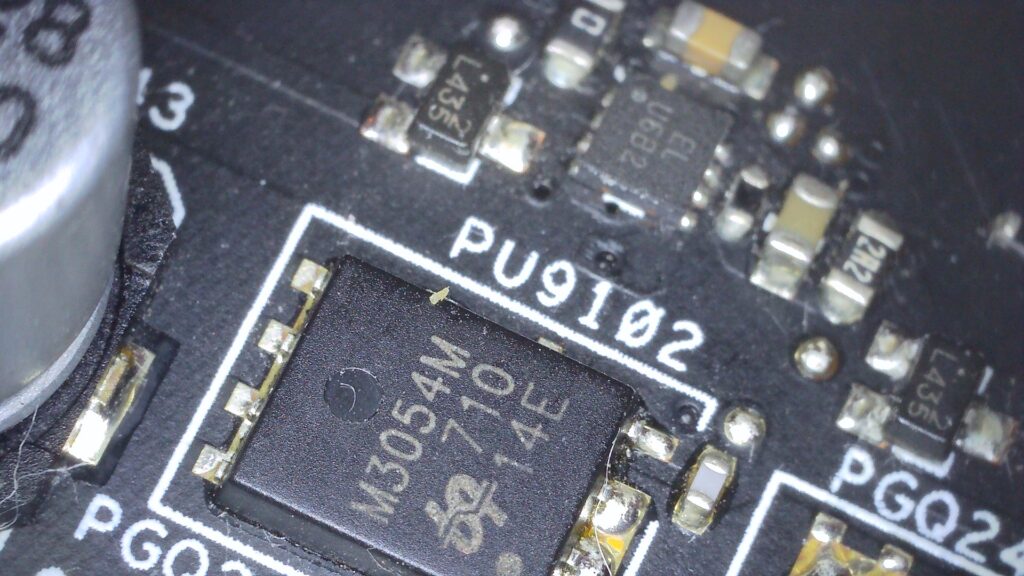
I have replaced all 3 high-side MOSFETs M3054M, I can see 3 phases, but no improvements in behaviour.
Onto the low-sides now, M3056M, changing all 3. Well, as I kind of expected, that didn’t improve anything either.
The unusual thing about this card is that 12V PCI (only has PCI) is seemingly unstable. It can be seen to drop to ~9V at intervals, causing other rails to drop. Quite possibly this is nothing to do with the VCore VRM, the fact that it showed a rough waveform under load could be a consequence of a 12V rail issue. Not sure how to find what is responsible? Possibly one of the other regulators is faulty under load.