Summary
- Cost £12.89, Seller Note “Untested”
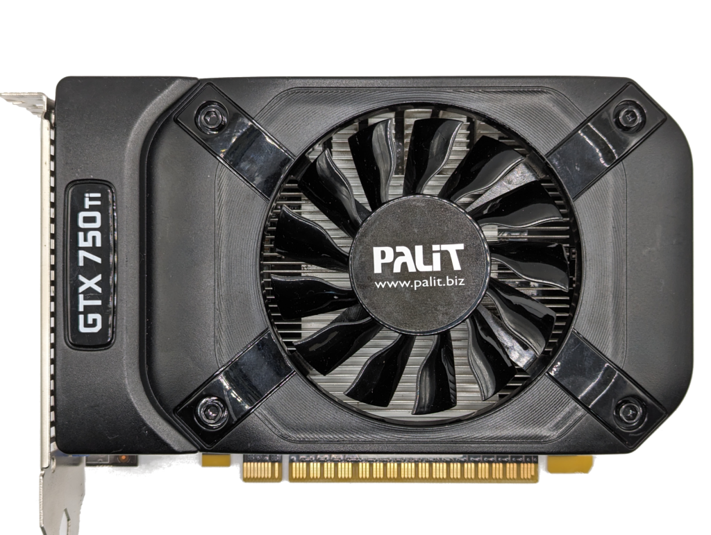
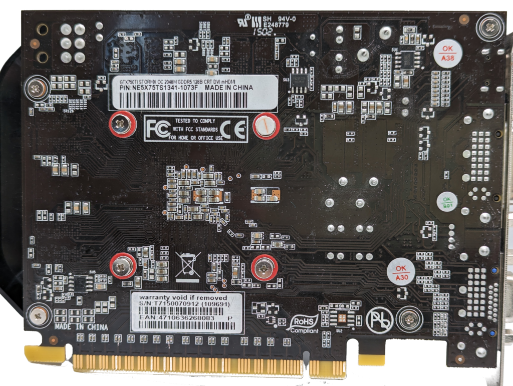
- 4 missing PCI capacitors, but decent condition and the warranty sticker is intact
- Has a mini-HDMI 1.4a port, the IO shield seems a little displaced
- Resistances (I will have to leave out 5V as I don’t want to break the warranty sticker)
- VCore – 10.3Ω
- VMem – 59Ω
- PEX – 346Ω
- 3.3V – 6.83KΩ
- 12V – 1.1KΩ (slot, no PCI-E on this card)
- (Linux test PC) The card loads drivers and runs Valley benchmark fine, at least for a short while
- Both the mini-HDMI and DVI seem to work fine
- I expect GPU-Z will show an impact to the PCI speed due to the missing caps
- Next steps:
- Test in Windows 10
- Check PCI speed in GPU-Z render test
- Fix missing caps
- Retest PCI speed to confirm if fixed
Investigating the PCI capacitor damage…
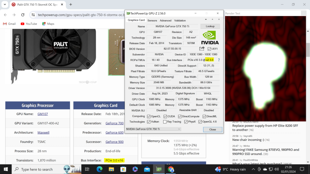
As expected, testing with the GPU-Z render test reveals the PCI speed is only running at x2, whereas it should be x16.
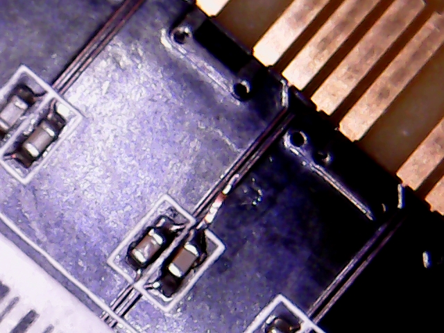
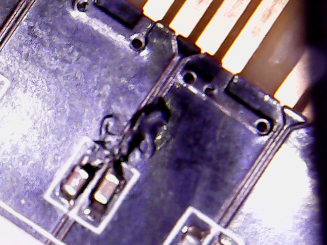
Taking a look at the damaged PEX capacitors, this one looks relatively OK:
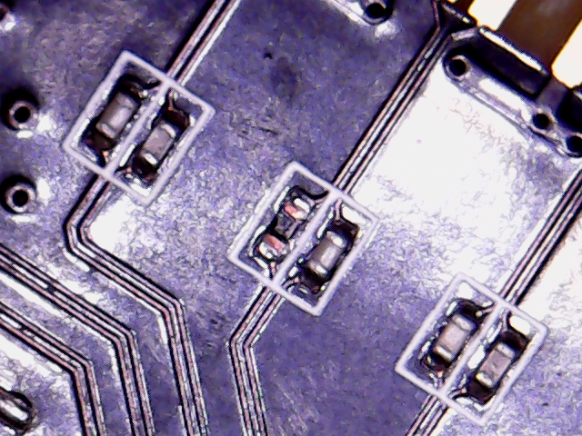
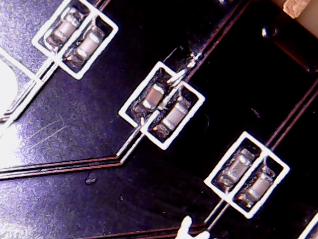
This one less so, the left one is relatively ok, the right one has a missing pad:
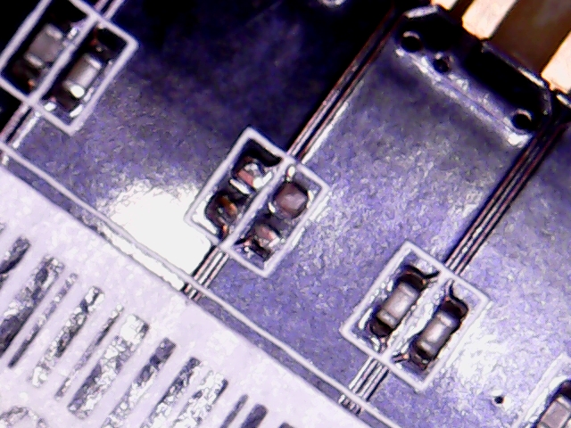
This one is also missing a pad:
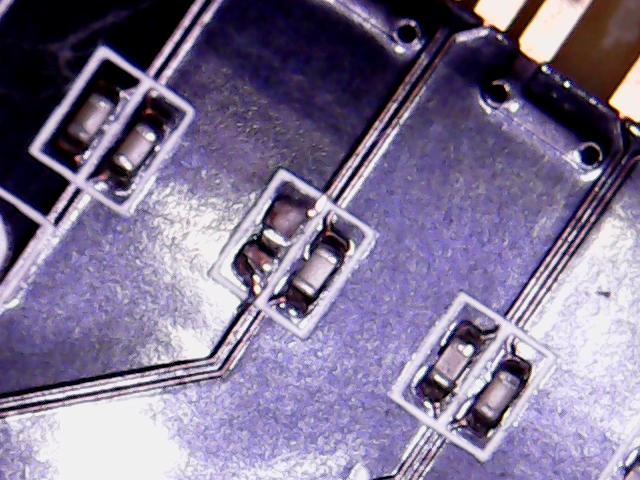
To prepare…
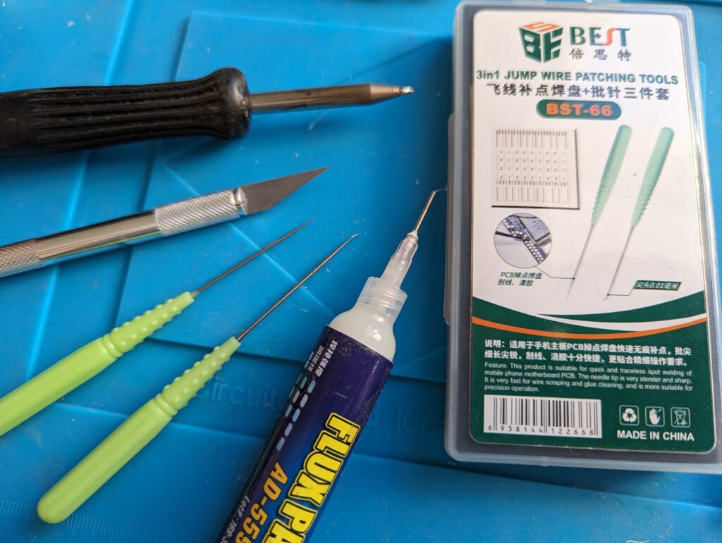
First, I’ll use some flux and solder to re-flow the pads/partial pads and scratch back the traces for the ripped pads and tin them. These are the tools I am expecting to use:
This one looks ready:
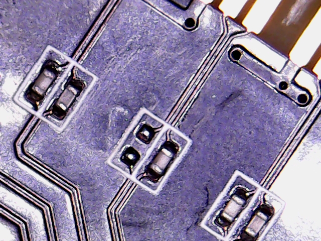
Here, one side is ready. I am hoping to solder a replacement trace/pad to the tinned trace for the other one:
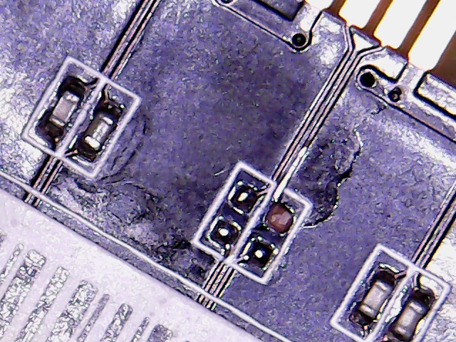
Similar approach for this ripped pad, I have tinned the scratched back trace:
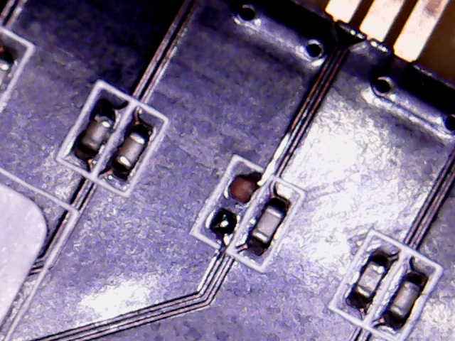
To repair…
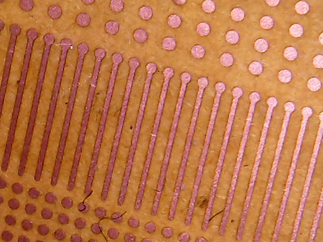
The trickiest part of repairing PCI lane damage tends to be replacing any ripped pads/traces with something suitable. I use the replacement trace with pad shown below (the pack is shown in the tools pick in the preparation section above). You could also use thin wire, maybe a strand of solder braid too.
The first one was simple enough to replace directly with a spare 220uF capacitor taken from a donor board.
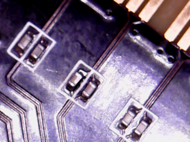
The remaining ones were a little more tricky to get the replacement trace to solder to the scratched-back original trace. Then I tin the new pad and solder the replacement 220uF capacitor in, first at the end with the original partial pad, then onto the replacement pad, taking care not to accidentally reflow the whole replacement trace (happens, just be patient and resolder):
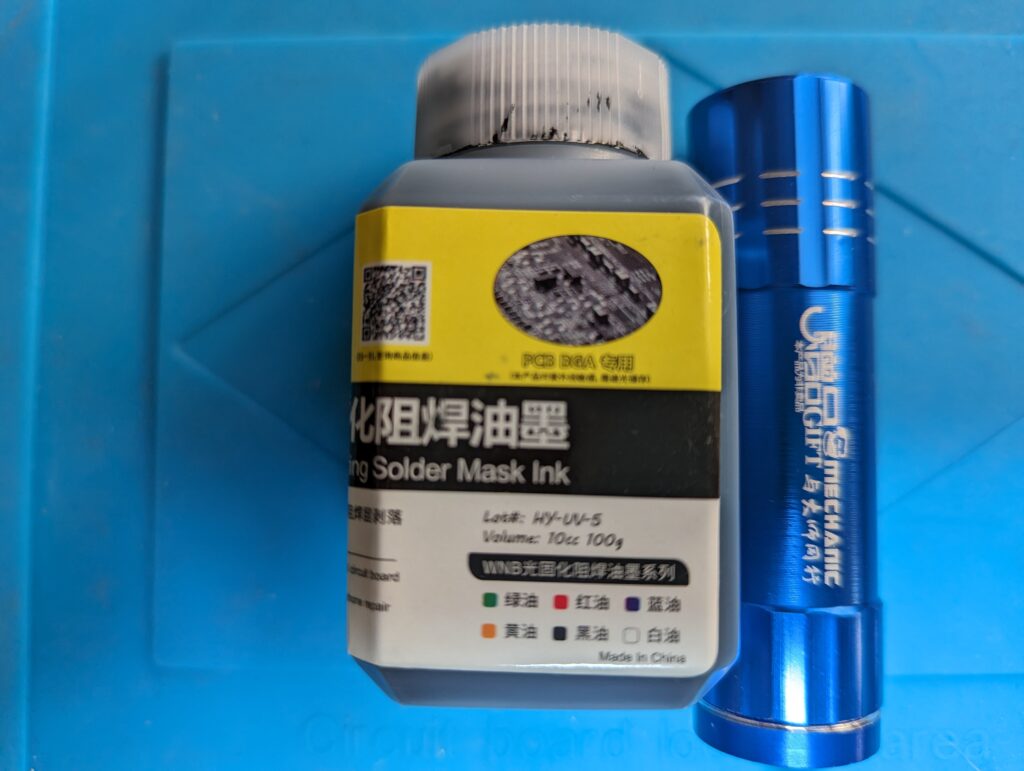
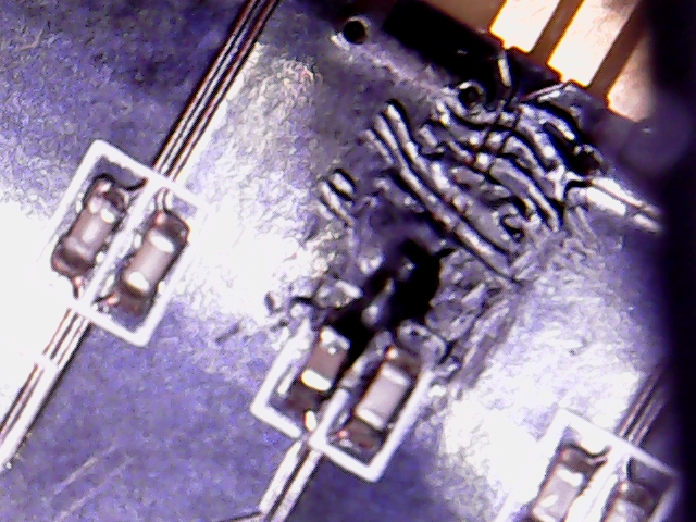
I’ll finish this off with some solder mask to cover the exposed new trace. I used this one and a small piece of stick from a cotton bud to apply the mask:
Not the neatest, but perfectly safe!
Testing…
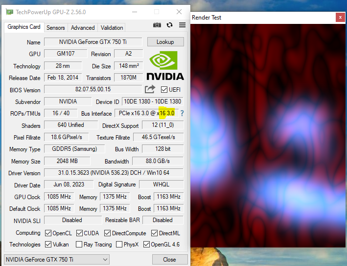
Success! We can see the PCI speed able to reach it’s full 16x 🙂
Learnings/Notes
- This card actually has 180uF PEX capacitors, which I didn’t have. I actually used ~220uF capacitors taken from a donor card, so there are a mix on there. I checked and this is OK, because the capacitors must actually be in a range 176-265uF (see page 19 of https://pcisig.com/sites/default/files/files/PCI_Express_Electrical_Basics.pdf)
got bunch of GTX 750 TI 1GB for just around 5 bucks. most of them had shorted vmem enable signal wich is easy fix, one card have low voltage on pex. but yeah, quite happy to see this cards running again…
cheers
Hi, ok, cool. Why was the enable pin shorted out of interest? Was it the VMem regultor itself that was shorted or a shorted capacitor on that circuit? Thanks, Rupert