Seller Note “Runs blank screen”
Summary
- This card seems in good clean condition and has it’s warranty sticker intact.
- The seller’s description suggests a possible running state and there are no obvious shorts on 12V or 3.3V, so without dismantling, a quick power-on test shows it starts for a few seconds then shuts down, no picture.
- I can see a damaged capacitor on the first PCI lane, this would be critical, so will resolder it directly.
- Now the card starts for a few seconds, shows a picture briefly (BIOS splash screen) and then shuts down.
- I probably should have started like I always do by measuring the resistances and not trusting the seller’s description, I just didn’t want to break the seal unnecessarily if the card actually turned out to be working (the other one he sold was mostly working).
- Resistances
- VCore – 1.2
- VMem – 95.2
- PEX – 304
- 5V – 3.2! (Short)
- 3.3V 767
- 12V 5.5K+
- OK, so there’s the source of the power issues.
- PCI capacitor in lane 1 was preventing detection.
- 5V rail was shorted due to a shorted driver for the middle 2 of the 6 VCore VRM phases.
- After replacing the regulator and driver, there were still problems, the donor card 5V regulator blew up! And the middle two phases weren’t running at all.
- The cause of the replaced driver not working appears to have been a faulty 1 Ohm resistor going high and dropping the VDRV voltage from 12v to 2v. Replacing this seem all phases working.
- Hopefully that’s everything, the card needs solid testing.
- This card has had it’s issues, but it seems in much better shape now!
Fixing the PCI Capacitor
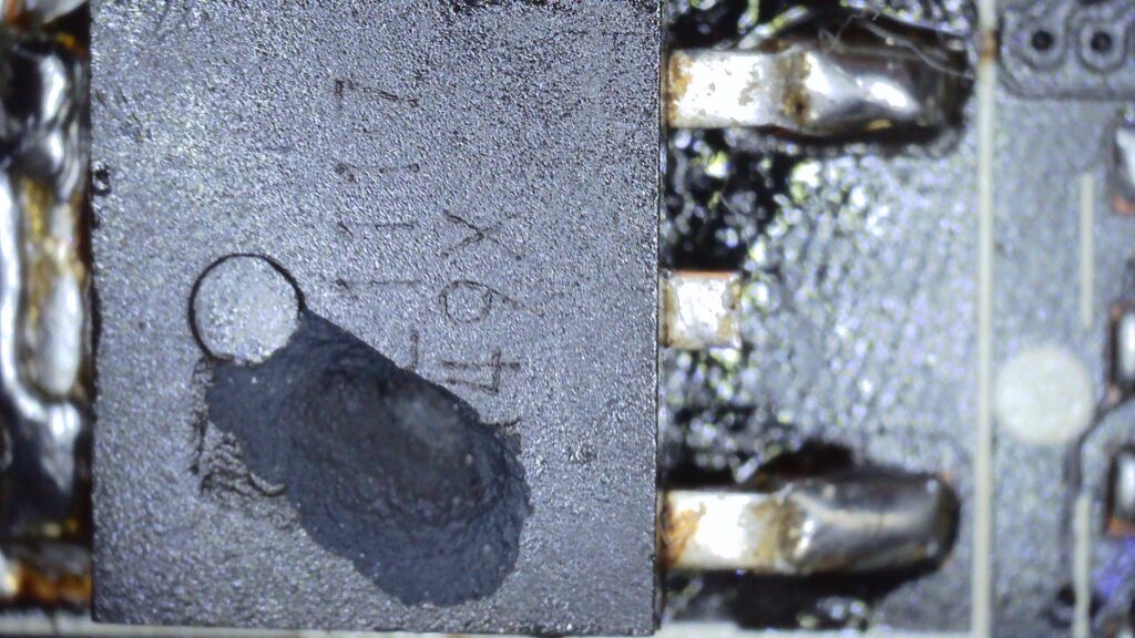
As they go, this could be worse. I can see the lower pad is ripped, but the upper one appears in good shape. I should be able to resolder this directly with some new leaded solder. If continuity is restored, and the card becomes functional, it might be worth completely removing the capacitor and replacing the broken pad, maybe exposing the trace a bit and using a little jumper wire or solder to improve the durability of the fix.
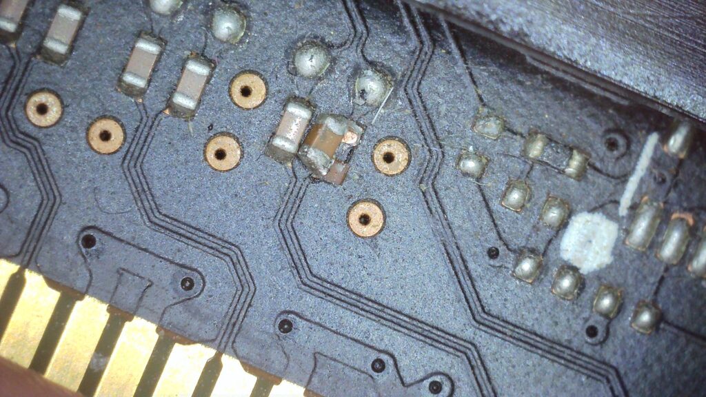
So replacing the capacitor restored the picture, if only briefly. I was like “yes! It’s working…. oh no it isn’t!” :-). After measuring the resistances, I can see why.
Fixing the 5V short
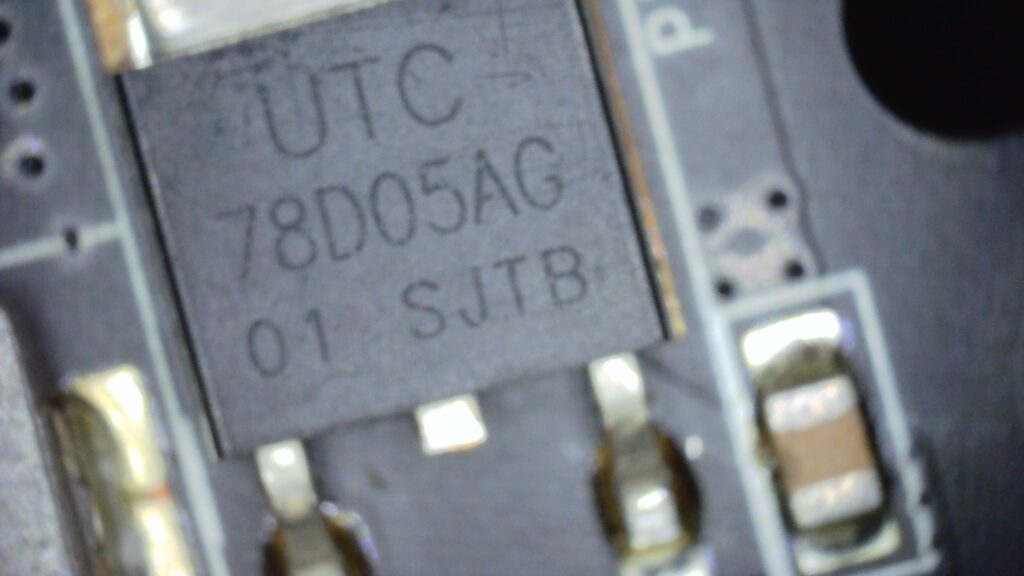
I started by injecting 1V into the 5V rail, but nothing obvious was getting hot or showing on the thermal camera. So, since it’s the 5V rail and the card has previously been running this way anyway, I decided to power on the card so as to test with more voltage. This is the 5V regulator, during power-on testing, it’s temperature reaches 145+ deg C! OK, so I wanted to eliminate the voltage regulator, so I removed it, but the short remained.
So, at least I know it probably wasn’t that, could still be faulty due to stress, but it’s not the source of the short. To investigate further, I decided to inject 3V into the 5V rail, this revealed the source of the short as being a MOSFET doubler (hot at 60 deg C).
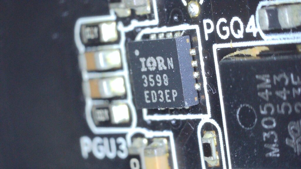
Removing this cleared the short. I don’t have any spares, so need to wait for some to come from China. Hopefully, there is a good way forward here! The driver is this one https://www.infineon.com/dgdl/ir3598.pdf?fileId=5546d462533600a4015355cdad66176d
Replacing the driver
Update 19/08/2022 – Replacing the 5V regulator and the card is seemingly working, but question marks over performance..
The first attempt to replace the 5V regulator after the short was eliminated ended badly as there was a small flare and part of the regulator blew up!
The donor card this 5V regulator was taken from looks baked and I can only assume the regulator was compromised or I somehow fitted it badly. Replacing the original one worked. I didn’t do this at first because I was concerned that the regulator was initially shorted, but it turns out it was only the driver that was. So hopefully the original 5V regulator still has some life in it.
Initial testing
- Passed Kombuster
- Passed 3D Time Spy, but with a somewhat below average score
Concerned that
- Hope that 5V regulator is reliable after initial problems
- Hope the VRM is working properly, need to test with an oscilloscope
Examination of VRM phases with an oscilloscope reveals that the middle two (of six phases) phases are not running. This explains my feelings toward the performance and GPU-Z readings. I am pleased it didn’t fail under load, I really should have checked this earlier! I would expect the driver isn’t working, possibly it wasn’t soldered properly or it’s failure caused the 5V regulator to blow up? A deeper dive is now needed to try and work out how best to restore it safely.
I need to work out
a) If there is an underlying issue that could have caused the original driver to short in the first place, because if present, this could have blown the new doubler and in turn the 5v regulator.
c) If no obvious fault presents itself, why is the new doubler seemingly not working? I could have soldered it wrong, it could have been faulty somehow, the PWM might have an issue…
First good to check some resistances relating to the non-working phases (I should have done this before!):
- Gate resistances for low and high side mosfets, especially in the phases that aren’t running
- Other resistances on the doubler
The high side is M3054M and the low side M3056M
There are 6 phases, the high side gate resistance should be 28K and the lowside gate resistance 47K. There is some small variances, but they are basically consistent. This doesn’t mean that all the MOSFETs in the non-working phase are good, but at least they don’t have shorted gates.
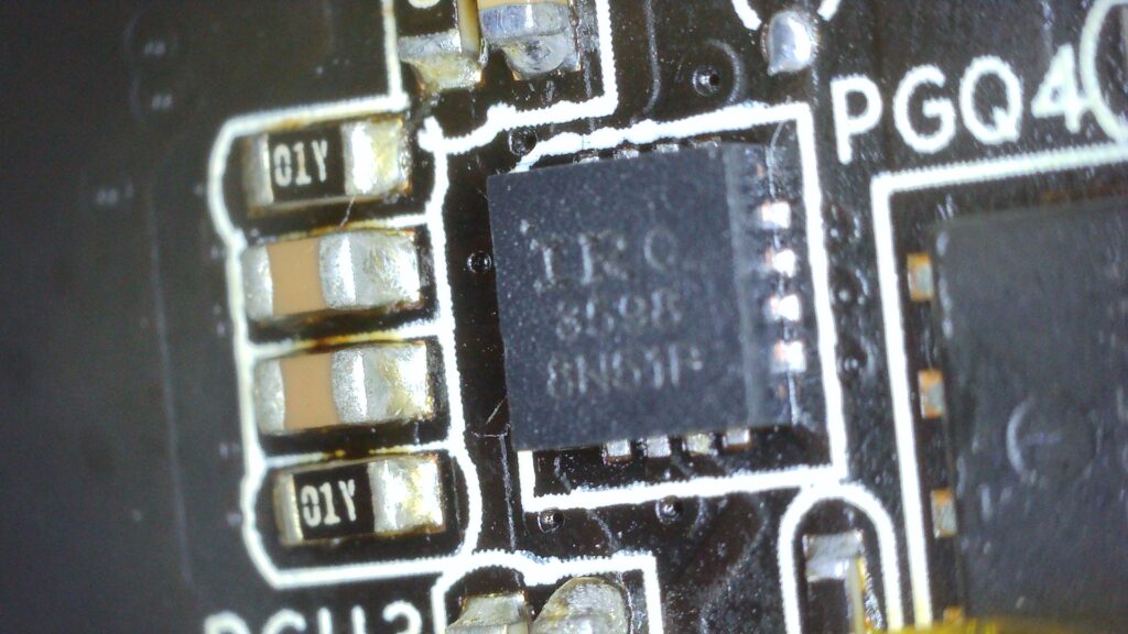
Deep dive on the driver
OK, so next to take a look at the driver
VCC – resistance 3.6K, 5V present (OK)
EN – is 5V and common to all 3 drivers
PWM1 – resistance 5M+, phase signal shown on oscilloscope (OK)
PWM2 – resistance 5M+, phase signal shown on oscilloscope (OK)
VDRV – the resistor supplying VDRV is showing12v (correct) on one end and 2v on the other. So the resistor must have become faulty and increased in value. Replace with 1 Ohm 0603
BOOT1 – should be 12V, but low voltage ~0-2V due to phase not running
BOOT2 – should be 12V, but low voltage ~0-2V due to phase not running
I will try replacing that VDRV resistor, as at least this seems definitely faulty.
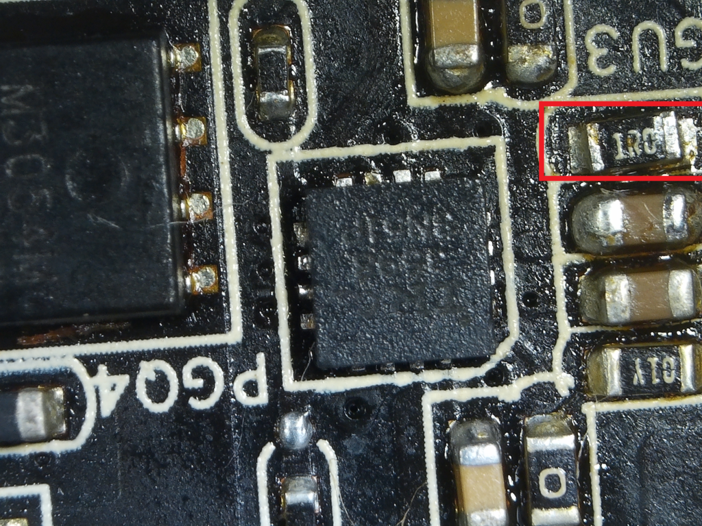
Yes! 12V to VDRV is restored and so are all the phases! All look clean on the oscilloscope now 🙂
Time to repaste, reassemble and recheck the performance …
Performance Testing Round 2
- Kombuster and Subnautica Below Zero are both looking smoother now. The graphs are looking a lot better in GPU-Z (No Vrel limit now, Power instead, the TDP is now ~91%, GPU load looks smooth at 100%)
- The fans on this card only seem to activate at 66 deg C.
- Timespy could be interesting, as the previous score was a bit below average. Now passes, a little below average.
- Furmark HD – seemed fine.
- Heaven HD Ultra looking good and running fine for more than 3 hours.
- OK, next I’ll run this in my main PC.
- I think this model of GTX 970 is fairly mid-range so should probably only score about average on 3d Time Spy. I also have another identical card to fix, so I can hopefully one day compare them.
- efficient cooling, I like the way this card maintains a temperature of around 65 deg C (hotspot <80 deg C) when under load.
- One potential issue is that, when horizontally mounted, at least in my machine, the card appears to flex quite a lot. Also, there is no cooling for the VRAM chips, hopefully, the lower running temperatures will help reduce the chance of BGA issues for card-flex.